diy solar

diy solar

Heltec (JK) 200A Smart BMS with 2A Active Balance

Yes - I put it into resources on this site. I also have the code on my Github page:


Note that there appear to be a few different versions of the BMS hardware/firmware and this protocol does not work with all. As soon as I have time I will document the whole thing, and see if I can make a more protocol-agnostic version.
 
I am soon to start charging up my cells for their first top balance. Is there any way for me to get into the BMS and start checking the config and getting familiar with it, can I hook it up to bench power supply and trick it some how into powering on?
 
i cant imagine this bms isnt used by some other manufactorer.
has anyone played with connecting the can tonan inverter and testing what info it gives when selecting a bigger name like pylontech, weco, soltaro,lib or lic ?
 
16 x CALB180 (SE180's)
So your nominal voltage should be about 3.2 x 16 = 51.2 volts. Do you have a power supply that can put that out at at least an amp? Then you will also need a 9 volt battery and a resistor of about 20-200 ohms, or a small light bulb. Connect the minus side of the power supply to both the large blue B- lead and the pin one of the balancer connector. Connect the plus side of the power supply to pin 25, the last pin of the balance connector. Then to make it turn on, you connect the plus side of the 9 volt battery to the minus side of the power supply, and the minus side of the 9 volt battery connect to the resistor (light bulb) and the other side of the resistor goes to the large black P- lead. You should hear a beep or two and the LED on the end of the BMS should come on. Once it is lit, you can disconnect the 9 volt battery. Now you can connect to the BMS with the BlueTooth App. With none of the balance leads connected, it will show a bunch of errors, but you should be able to go in and look at the settings page and get it configured for your system. If it won't stay on, it could be due to the open balance wires. You can try using a string of 16 100 ohm resistors. With the resistors string connected across the power supply, each one will have about 3.2 volts across it. Connect the balance leads to each resistor junction. You end up with 17 connections. It will likely still throw some kind of error, because it pulls some current on each balance lead to measure the wire resistance to each cell. The 100 ohm resistors will like like very bad connections. But if it makes it past the test, and you can turn balancing off, it should then report the voltage across each resistor. The default is for 24 cells, so you need to change that to 16 in the settings, then power it off and back on again. May need to use the 9 volt battery again.
 
So your nominal voltage should be about 3.2 x 16 = 51.2 volts. Do you have a power supply that can put that out at at least an amp? Then you will also need a 9 volt battery and a resistor of about 20-200 ohms, or a small light bulb. Connect the minus side of the power supply to both the large blue B- lead and the pin one of the balancer connector. Connect the plus side of the power supply to pin 25, the last pin of the balance connector. Then to make it turn on, you connect the plus side of the 9 volt battery to the minus side of the power supply, and the minus side of the 9 volt battery connect to the resistor (light bulb) and the other side of the resistor goes to the large black P- lead. You should hear a beep or two and the LED on the end of the BMS should come on. Once it is lit, you can disconnect the 9 volt battery. Now you can connect to the BMS with the BlueTooth App. With none of the balance leads connected, it will show a bunch of errors, but you should be able to go in and look at the settings page and get it configured for your system. If it won't stay on, it could be due to the open balance wires. You can try using a string of 16 100 ohm resistors. With the resistors string connected across the power supply, each one will have about 3.2 volts across it. Connect the balance leads to each resistor junction. You end up with 17 connections. It will likely still throw some kind of error, because it pulls some current on each balance lead to measure the wire resistance to each cell. The 100 ohm resistors will like like very bad connections. But if it makes it past the test, and you can turn balancing off, it should then report the voltage across each resistor. The default is for 24 cells, so you need to change that to 16 in the settings, then power it off and back on again. May need to use the 9 volt battery again.
GMX, thanks for the lengthy reply, the PSU wont go above 47V, I did try but couldn't get it to come to life.
 
47 volts should be enough, the instructions I got said 40 volts minimum.

Check out this video
At just after 11 minutes in he starts talking about how to turn it on. He uses a 2S LiPo battery, but a 9 volt should do it just fine.
 
47 volts should be enough, the instructions I got said 40 volts minimum.

Check out this video
At just after 11 minutes in he starts talking about how to turn it on. He uses a 2S LiPo battery, but a 9 volt should do it just fine.

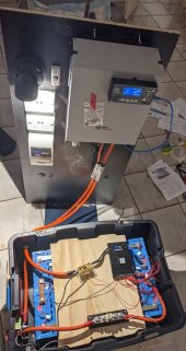
All up and running now, my bench PSU is weird and wouldn't work, but I ended up getting it all going not long after anyway.
Excuse the mess, its currently in a temporary mobile setup, it will be powering the off grid shack build.
Loving the BMS and app too!
 

Attachments

  • OGPP.jpg
    OGPP.jpg
    172.8 KB · Views: 52
I have an issue with charging via grid with my MPPSolar all in one.
Currently set to 30A charging.

The battery pack is nearing full charge, I have set cell OVP to 3.5v for now.
But the BMS is not tailing off the incoming current from the MPPSolar, so 30A is smashing the pack then it keeps hitting OVP.

I have also noticed when it does this, that the -P voltage is stuck 3v higher than the actual real pack.
E.g. Pack actually at 53.85v, but when measuring Main+ and P- it says 56.43v!!!!
I can only get it back by disconnecting the BMS, then it reads correctly.

Any ideas on what settings I have messed up?
Use a multimeter and measure the voltage of the pack. Then use the voltage calibration on the bms setting and insert the correct voltage of the pack. Then you should be ok.

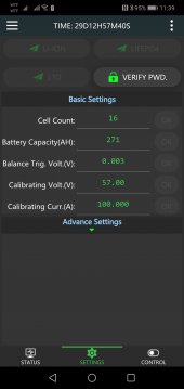
After calibration, measure every cell voltage to see if it matches what the bms reports.Screenshot_20210626_113923_com.jktech.bms.jpg
 
Use a multimeter and measure the voltage of the pack. Then use the voltage calibration on the bms setting and insert the correct voltage of the pack. Then you should be ok.

After calibration, measure every cell voltage to see if it matches what the bms reports.

A little more fiddling. It appears the issue is only present when the MPP inverter is plugged into the wall power, as soon as I unplug AC-In the voltage reading on the MPP Solar drops to a correct reading. Weird.

I cant hook up my panels at this stage to see if they cause a voltage rise on the MPP inverter yet unfortunately.

BMS voltage and actual pack voltage are spot on and have been calibrated. So its not looking like a BMS issue.
 
A question regarding when the cells reach near full capacity.
Are you seeing the BMS reducing the charge current, because I am not.
Would appreciate some screen shots of your working Advanced settings, to put my mind at ease.
 
A question regarding when the cells reach near full capacity.
Are you seeing the BMS reducing the charge current, because I am not.
Would appreciate some screen shots of your working Advanced settings, to put my mind at ease.
Check if your inverter as any calibration for the AC voltage and amps.
 
Yes a see my amps reducing, but in my inverter i select 57 amps and it only stops at 58,but this is a inverter problem, not bms. The bms doesnt regulate amps, it only protect the battery for overvoltage and under voltage in the cells. The inverter must regulate the charging.
 
MikeSolarPT is correct. The BMS does not adjust charge current in any way. It can't do that. That is the job of the charger. The BMS is just a watch dog. It can only disconnect the battery if the voltage goes too high.

You need to set the proper absorb voltage in the MPPSolar hybrid inverter/charger. I do not know their menus, so you will need to go through the manual or menus to find these settings. The charge absorb voltage needs to be lower than the OVP voltages set in the BMS. The BMS should only hit disconnect if something goes wrong. It looks like you are running 16S LFP cells. The BMS should be set for 3.65 volts per cell and 58.4 volts overall. But then set the MPP charging to about 54.4 volts for the absorb voltage. That should give enough room to allow a decently balanced pack to not have a cell go too quickly into the upper knee. If you do still find a cell hitting the OVP, then you may need to lower the absorb voltage even more until your pack is better balanced.

In the BMS, set the balancing to start at 3.2 volts per cell, so it can try to hold down any cell that does start going into the knee as the pack is charging up. That should prevent over voltage protect from kicking in. As the pack goes into the absorb cycle, the current should taper off with the voltage holding. This dropping charge current will give the balancer more time and authority to pull the cells into a good top balance on each charge cycle. If your pack is well top balanced and matched, the balancer won't have to work much at all. If your pack is well balanced, you may be able to set the cell delta voltage down pretty low. I have mine at just 0.006 volts, but letting it go to 0.010 to 0.015 is acceptable for packs that are not as ell matched. As good as the balancing is, it is not 100% efficient, so having it work to balance to a super low delta voltage is actually wasting some energy. On most resistor balancers, they literally just turn any extra voltage in a high cell into heat. Our JK/Heltec balancer does try to capture some of the extra voltage and use it to charge the lowest cell, an maybe 80% of the energy can be captured, so it is a lot better.

The reason for the voltage difference when charging, at rest, and discharging is likely due to the total resistance in the system. At just 30 amps, it only takes a few milliohms to show a voltage increase during charging, and a voltage drop while inverting. If you feel that voltage change is too high, you may need to check all of your connections and make sure nothing is loose or oxidized. 0.01 ohms (10 milliohms) between the battery bank and the inverter/charger would cause a 0.3 volt change for a 30 amp change in current. In my system, I had one cable between cell 10 and 11 that had a little more resistance than the buss bars between the rest. This would cause the balancer to try and discharge those cells while charging, and then try to push energy back into those cells while discharging. I added another cable in parallel so the voltage change is now much closer to the other buss bars, and then I opened up the cell delta from 0.003 to 0.006 and now my balance basically never runs. I found this when I saw the balancer kept hitting the same two cells. When I checked with my meter, I saw the true cell voltages were fine, it was the drop in the 18 inch long #2 awg wire compared to the 2 inch long copper bars between all of the other cells.

The only time I had my JK BMS shut down my battery was when one of the balancer wires lost connection. It appears the wire was crimped on the insulation, not on the stripped wire. After a tiny bit of oxidation, the connection failed. So the BMS saw the cell on either side of the failed balance wire as 0 volts. It opened the discharge mosfets to protect the system from any damage. Once I found the bad lead and repaired it, the system worked fine again. I do plan on making a complete new balancer harness as the crimps on 1/4 of the leads just don't look that good, and I now have 2 more cells showing a little more resistance on the balance wires again. It is not enough to cause a problem yet, but it might in the future. This is one of the reasons I am adding a second battery bank with a separate BMS. If one does fail, I will still have the other battery to run on.
 
For anyone that read my previous posts, I made that little wire wound resistor/moment switch jig and it worked a treat.
 
For anyone that read my previous posts, I made that little wire wound resistor/moment switch jig and it worked a treat.
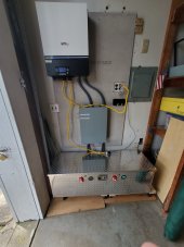
Yeah, I built mine in to the battery box. Extreemly useful. The little red push buttons for each 16s bank in the box is connected to a resistor in parallel with the each battery switch main.
 

Attachments

  • 20210516_135033.jpg
    20210516_135033.jpg
    131.3 KB · Views: 47
Yeah I don't have a box, my cells are compressed, but sit inside a large metal cabinet with the rest of the gear for easy access.

My point was more that I'd done it as I showed in my picture, which is slightly different to how others have done it, mainly because I do not have a master on/off.
 
Hi, does anyone know if it's OK to parallel the Heltec/JK BMS? I want to build 2 16S packs, each w/ a BMS, and then parallel the packs. I read JBD's spec sheet, and it seems to specifically parallel BMS w/ this statement:

"Direct parallel connection of batteries is not supported (there is the problem of high current discharge from high voltage batteries to low voltage batteries due to direct parallel connection of batteries)"

I can't think of a case where hooking up battery banks in parallel would cause a high current discharge between them, unless 1) one of them shorts out or 2) you connect a batteries together that are in different states of charge. If the 2 packs are at the same SOC when you hook them up, this shouldn't be an issue, right?
 
Back
Top