diy solar

diy solar

House burned down

A few questions -

What sort of regular maintenance and inspections do you do for your battery strings?
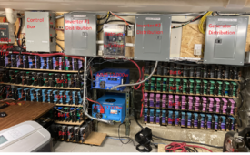
Look at them now and then. After the 6+ years in mild ambient conditions I've gained enough confidence that I don't worry about them physically day by day. Monitoring (Batrium + Camera) + data history for trends is sufficient to alert me to trouble for now. Maybe after 10 more years and I start to get serious, uneven capacity degradation?
1715203519439.png1715203348582.png

Do you turn them all off at once or one at a time and cycle through them?
All on, all the time. Not sure why I'd want to 'cycle through them' other than some kind of individual battery capacity testing. Individual battery testing has not been needed so far... year 6+ and ongoing.

Do you have written instructions for the maint so someone else could do them if you were out of town and/or incapacitated?
All is breaker'ed and labeled (see below). All breakers off and the system defaults to grid / becomes inactive. Order of on/off doesn't matter + individual components will shut off appropriately on their own if necessary.

Do you have documentation on your whole system design?
Yes but the only one who's used it is me. The most useful has been the PV wiring arrangement down to the panel level.

Do you have documentation on startup and shutdown?
Quick Disconnects outside at the arrays (required by code). At the control area... labeled Breakers for
- PV -> Charge Controllers (required by code - labeled with voltage/current)
- Charge Controllers -> Battery
- Battery -> Inverters.
- 400a BMS controlled shunt-trip for battery bank - shuts off 100% of all loads, no battery activity at all.
- Standard US 240v/120v distribution box / breakers.

Midnite Classic charge controllers don't care about PV vs Battery on/off order - so the overall order of turn on/off doesn't matter. All off and default is grid.

I've trained my wife/extended-family to turn all breakers off to default to grid only.


Did you do a build thread?
Not on this forum.
 
Last edited:
Look at them now and then. After the 6+ years in mild ambient conditions I've gained enough confidence that I don't worry about them physically day by day. Monitoring (Batrium + Camera) + data history for trends is sufficient to alert me to trouble for now. Maybe after 10 more years and I start to get serious, uneven capacity degradation?
View attachment 214123View attachment 214122


All on, all the time. Not sure why I'd want to 'cycle through them' other than some kind of individual battery capacity testing. Individual battery testing has not been needed so far... year 6+ and ongoing.


All is breaker'ed and labeled (see below). All breakers off and the system defaults to grid / becomes inactive. Order of on/off doesn't matter + individual components will shut off appropriately on their own if necessary.


Yes but the only one who's used it is me. The most useful has been the PV wiring arrangement down to the panel level.


Quick Disconnects outside at the arrays (required by code). At the control area... labeled Breakers for
- PV -> Charge Controllers (required by code - labeled with voltage/current)
- Charge Controllers -> Battery
- Battery -> Inverters.
- 400a shunt-trip for battery bank
- Standard US 240v/120v distribution box / breakers.

Midnite Classic charge controllers don't care about PV vs Battery on/off order - so the overall order of turn on/off doesn't matter. All off and default is grid.

I've trained my wife/extended-family to turn all breakers off to default to grid only.


Not on this forum.

Thanks for the answers, always good to know.

Things get a little hot and the fan is needed?


Where in the picture are your fuses and shunts?
 
Look at them now and then. After the 6+ years in mild ambient conditions I've gained enough confidence that I don't worry about them physically day by day. Monitoring (Batrium + Camera) + data history for trends is sufficient to alert me to trouble for now. Maybe after 10 more years and I start to get serious, uneven capacity degradation?
View attachment 214123View attachment 214122


All on, all the time. Not sure why I'd want to 'cycle through them' other than some kind of individual battery capacity testing. Individual battery testing has not been needed so far... year 6+ and ongoing.


All is breaker'ed and labeled (see below). All breakers off and the system defaults to grid / becomes inactive. Order of on/off doesn't matter + individual components will shut off appropriately on their own if necessary.


Yes but the only one who's used it is me. The most useful has been the PV wiring arrangement down to the panel level.


Quick Disconnects outside at the arrays (required by code). At the control area... labeled Breakers for
- PV -> Charge Controllers (required by code - labeled with voltage/current)
- Charge Controllers -> Battery
- Battery -> Inverters.
- 400a BMS controlled shunt-trip for battery bank - shuts off 100% of all loads, no battery activity at all.
- Standard US 240v/120v distribution box / breakers.

Midnite Classic charge controllers don't care about PV vs Battery on/off order - so the overall order of turn on/off doesn't matter. All off and default is grid.

I've trained my wife/extended-family to turn all breakers off to default to grid only.


Not on this forum.
There's no fusing in your batteries? Just the 400A shunt trip to disconnect it?
 
There's no fusing in your batteries? Just the 400A shunt trip to disconnect it?
It's 18650 - and each of the 12,000+ individual cells are connected to the buss with fuse wire (based on Tesla car battery design). Thus, don't need fusing at the pack or battery level the way one might want for LifePo4 cells.

If a short were to occur, it's not clear weather the ABB SACE would trip or fuse wires would blow first or both - the entire powerwall would be rendered toothless in short order. It would be a huge 'rebuild' effort :)

The ABB SACE could trip at 400a overall load (or charge) but the powerwall itself has ~2,000a @ 48v potential so the fuse wire won't burn just for a 400a load. It would take short at a pack or battery or powerwall level for the fuse wires to burn - but that's what they're for.
 
Last edited:
  • Like
Reactions: D71
It's 18650 - and each of the 12,000+ individual cells are connected to the buss with fuse wire (based on Tesla car battery design). Thus, don't need fusing at the pack or battery level the way one might want for LifePo4 cells.

If a short were to occur, it's not clear weather the ABB SACE would trip or fuse wires would blow first or both - the entire powerwall would be rendered toothless in short order. It would be a huge 'rebuild' effort :)

The ABB SACE could trip at 400a overall load (or charge) but the powerwall itself has ~2,000a @ 48v potential so the fuse wire won't burn just for a 400a load. It would take short at a pack or battery or powerwall level for the fuse wires to burn - but that's what they're for.
Ok, I understand now, each cell is fused so no worries at all there for a runaway situation like the OP had.
 
Certainly puts the fear of god into you when you read something like this. Thankfully he and his family are safe but almost certainly a life changing event. I read about an electronic engineer who had setup lifepo4 batteries from china in germany and house also destroyed but from an explosion.


I think ill start planning to move all my kit out to the shed.
 
  • Like
Reactions: D71
Certainly puts the fear of god into you when you read something like this. Thankfully he and his family are safe but almost certainly a life changing event. I read about an electronic engineer who had setup lifepo4 batteries from china in germany and house also destroyed but from an explosion.


I think ill start planning to move all my kit out to the shed.

Make the shed fireproof first
 
Certainly puts the fear of god into you when you read something like this. Thankfully he and his family are safe but almost certainly a life changing event. I read about an electronic engineer who had setup lifepo4 batteries from china in germany and house also destroyed but from an explosion.


I think ill start planning to move all my kit out to the shed.
I think the speculation was that the boiler pilot light may have have ignited the outgassing hydrogen from the cell(s).
 
Anybody care to speculate why the blue sea fuse holder says this if that is not true?

A fuse like a Class-T can in some circumstances 'explode' in the sense that sand and bits of metal can come flying off in case of a short. They quench the arc very well, but in the process there might be some 'mechanical deformations' so to speak. The cover over the fuse holder keeps these bits in one place.

Doesn't happen often, but it's possible. By the way, this is a direct short and how a Class T deals with it (without the explosion - the sparks are from the contact):

 
It isn't ridiculous now is it? Afterall, more is better and more after that is even better yet.

This is what you sound like reading the comments.

Rant over. :)

What, Me sound like?

1715213708702.png

If multiple strings are in parallel, can one bad one get cooked and vent, without fuses blowing to isolate it?

I suggest isolating bad string of cells in the event problems are detected. Contactor or shunt-trip breaker, under control of BMS.
 
Relevant note. I was hooking up my blue Sea class T fuse and holder, and there is a sticker on the cover that says something like explosion proof when cover in place. This indicates to me that the class T fuse contained within the holder is not ignition proof without the cover, I’ll get a photo next time. I’m up there.
 
Relevant note. I was hooking up my blue Sea class T fuse and holder, and there is a sticker on the cover that says something like explosion proof when cover in place. This indicates to me that the class T fuse contained within the holder is not ignition proof without the cover, I’ll get a photo next time. I’m up there.

Are you stuck in a time loop? ;) ... or is this the Matrix all over again.
 
National Electrical Code (NEC) 2020
The container in that context is the smallest element that is dealt with in the field for a raw battery, like a 12v brick. When you have a UL 48V pack that does not need a "container," but it could require spill containment.

Cell - single electrolytic unit
Module - assembly of one or more cells into a UL package
String - series collection of cells or modules with a single external current path
Battery - collection of one or more strings for a complete system.
 
Being that people use a single 12 volt car battery with cables to weld in the field, it’s very possible.

"He never actually touches the other post and then he draws the arc"

I don't buy the part about it jumping an airgap to initiate the arc either.
Higher voltage needed to ionize air and make a spark.

Once you've got an arc, then you can pull it.
(But I'm not good under 125A on my 80Vrms buzz box.)
 
"He never actually touches the other post and then he draws the arc"

I don't buy the part about it jumping an airgap to initiate the arc either.
Higher voltage needed to ionize air and make a spark.

Once you've got an arc, then you can pull it.
(But I'm not good under 125A on my 80Vrms buzz box.)
ok I have only welded for about 40+ years at this point in my life. when using DC current for welding the object is to start the arc without touching the base metal. professional welders do that all the time. beginners drag the electrode across the base metal to start the current flowing.

ever watched a tig welder? you hold the tip of the electrode about 1/8" and start welding. thats from a low of 5-10 volts for really thin metal, up to the limits of your welder. if you are running say 48 volts that gap can be as large as your shielding gas will cover.
 
Forgot to add this csst gas line is reported as cause of that gas line failure … something about…. some how during storm …. lightning went through popped hole.
“Gas line and popped a hole in it.” This csst type gas line is reported cause fires all over USA and was common in homes and is still sold. They say it was not bonded correctly…why lightning takes it out when strike happens nearby. They say it is .008” thick wall. Still sold all across the country.

View attachment 213807
View attachment 213808
Example …. Stored energy is dangerous. Got csst flex type gas lines in your home? The way some connections are made it is impossible to really bond it. So…… if home had fire place in that hoa it had csst.

The Arson was most likely the maker of the csst type gas line in described home for last post. Installer gets the blame. Buy beware.

Caveat emptor


That csst is builder - govt approved.
yeah they use that stuff here in japan as well, but the regulator for the gas is designed that if it flows gas over X amount in x time shut off. it is set to see sudden large amounts in the case of a ruptured pipe, or a low/slow amount over a period of time. slow leaks. the damn regulator costs more than the two propane tanks cost

IMG_2155[1].JPG

it can be a real pain in the ass when roasting a turkey or a ham in the US oven. had to put in special paperwork to get them to reprogram it to accept how a US gas oven works.
 
  • Like
Reactions: D71

diy solar

diy solar
Back
Top