diy solar

diy solar

How to run AC input off generator only with 2 Growatt 5000es inverters and auto transformer…

Offgrid100

New Member
Joined
Feb 4, 2022
Messages
2
I could use some clarification if anyone can help. I am 100 percent off grid and want to run my generator as the AC input to my Growatt 5000 es inverter. These are 240v inverters so the input must be 240v correct?

If that is true, I still have an issue because there are only three terminals for me to run wires to. There is a L, G, and N. Won’t there be four wires if I run 240 from my generator?

Sorry if this is a silly question but it has me stumped. Thanks in advance for any help you can offer.
 
you wouldn't connect generator N to anything.
 
Hello - Not sure of your installation but 240 volts can use only three wires - there is two legs at 110 volts on each leg, and a neutral wire.
Ether leg to neutral, gives you 110 volts. The volatge between the two hot legs is 240 volts. Be careful and use a voltmeter to confirm the voltages before hooking it up to your inverter.
Regards - Mike
This is true, but irrelevant to the op question.
 
I could use some clarification if anyone can help. I am 100 percent off grid and want to run my generator as the AC input to my Growatt 5000 es inverter. These are 240v inverters so the input must be 240v correct?

If that is true, I still have an issue because there are only three terminals for me to run wires to. There is a L, G, and N. Won’t there be four wires if I run 240 from my generator?

Sorry if this is a silly question but it has me stumped. Thanks in advance for any help you can offer.
Because you are using a European inverter, its N would go to your generator L2, and as said above, N wouldn't ne attached.
 
And make sure your 240v/120v generator does not have its neutral connected to generator chassis ground.

If generator has a 120v/240v switch, make sure it is set to 240vac.
 
Because you are using a European inverter, its N would go to your generator L2, and as said above, N wouldn't ne attached.
It is actually the American version of the inverter from Signature Solar. Thanks for your response.
 
It is actually the American version of the inverter from Signature Solar. Thanks for your response.
No..post.... it isn't.
It is a modified euro inverter with an auto transformer added to provide neutral balancing.
 
Many of the 230vac only inverters have ability to switch between 50 Hz and 60 Hz. They call it American version because it can do 60 Hz.

It is still just a 230vac only inverter and may even have one leg of 230 vac tied to inverter case ground.
 
I could use some clarification if anyone can help. I am 100 percent off grid and want to run my generator as the AC input to my Growatt 5000 es inverter. These are 240v inverters so the input must be 240v correct?

If that is true, I still have an issue because there are only three terminals for me to run wires to. There is a L, G, and N. Won’t there be four wires if I run 240 from my generator?

Sorry if this is a silly question but it has me stumped. Thanks in advance for any help you can offer.
With the growatt SPF 5000 ES L=Line 1, G=Ground and N=Line 2. L1 & L2 are 120 volts each. No neutral is connected to the growatt inverter at AC in or AC out. The neutral is supplied to the neutral bar in the breaker box by the split phase transformer.
 
  • Like
Reactions: Rho
With the growatt SPF 5000 ES L=Line 1, G=Ground and N=Line 2. L1 & L2 are 120 volts each. No neutral is connected to the growatt inverter at AC in or AC out. The neutral is supplied to the neutral bar in the breaker box by the split phase transformer.
No...
In order for the lines to be 120V each, there needs to be a mid tie point inside the inverter.
The output is 240V between L and N.
The auto transformer is there to produce a fake N that balances to 120V in the panel.

Not the same as what you are saying.

Not 120V on each leg, it is 240V without any 120V out.
With the growatt SPF 5000 ES L=Line 1, G=Ground and N=Line 2. L1 & L2 are 120 volts each. No neutral is connected to the growatt inverter at AC in or AC out. The neutral is supplied to the neutral bar in the breaker box by the split phase transformer.
I answered Offgrid100's question ( how to hook up AC in on the Growatt inverter ) correctly and I noticed you haven't answered it at all. I ran power to the inverter from a 50Amp breaker to AC in and connected it as I answered before. G to G, L1 to L1, and L2 to N. That is the way SS says to wire it and it is the way EVERYONE on U-Tube is showing it done. I don't believe the inverter knows whether the AC in is coming from the Grid or my Generator. I have both. Supervtech, simple answers help. Explaining theory or the origin of electricity just complicates the issue and confuses the person asking the question more. . .
 
Hello,
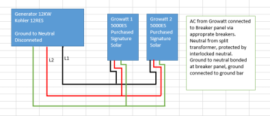
could someone please tell me if my generator set up below is correct. In particular ground to neutral bonding . I'm a little confused whether the generator needs to have the ground connected at the generator source to an independent grounding bar. Its currently connected to the neutral by manufacture default, but I intend to disconnect this and set up the system as below.
Appreciate the help.
1649765360082.png
 
Many of the Chinese inverters have a N-G bonding relay that disconnects N-G bonding at inverter when an AC input is applied so the grid N-G bonding takes over responsibility for N-G bonding. The 'PCB screw' in the middle of PCB disconnects the European neutral to chassis ground so the inverter's neutral is permanently floating which is required to connect an auto transformer to provide split phase 240/120 vac.

Do not use generator neutral as it can cause 120vac loading conflict with auto transformer resulting in auto transformer trying to correct any 120vac imbalance between auto transformer and generator. It will eat up some of the transformer power handling capability. Make sure generator neutral to ground is not connected.

Generator frame ground should be connected to distribution breaker box case, inverter case ground, and auto-transformer box ground. Your distribution breaker box should have grounding stake to earth ground. Auto transformer center tap neutral should be brought back to distribution breaker panel where it is connected to ground via the panel's neutral bus bar grounding point.

You might have problems with GFI breakers tripping due to inverter EMI filters having capacitors connected to inverter chassis ground.
 
I have an old Honda 6000 generator that works perfectly . It is not an inverter generator . Can this be connected to Growatt Spf6000dvm? What are the specifications for a generator to be used on the growatt if there are any? Any assistance needed
 
On a constant rpm synchronous generator the most common issue is governor stability to keep rpm constant. Hybrid inverters synchronizes AC phase to AC input and inverter cannot track varying AC input frequency causing it to release from generator.

The rpm wobble cannot result in AC output exceeding about 0.3 Hz per second of AC output frequency. The inverter phase tracking must be slow to avoid too much freq shifting too quickly that may upset inductive motor loads. A DVM freq counter function will not detect this small amount of freq instability. Simple way to detect it is to listen to generator. It should be smooth and constant with no surging 'wha-wha' varying pitch sound. Just a dirty carburetor air filter or fuel filter can cause governor instability.

Second most common issue is the generator rpm being so far off the AC output frequency is not within lock freq range of inverter. Usually there is a set screw to adjust engine rpm and can be done with a DVM freq counter function measuring AC output frequency.

P.S. Just to be sure, must not swap the L1-L2 AC inputs between inverters' L-N inputs. Hopefully the inverters' parallel sync control is smart enough to detect reversed L1-L2 connections. Inverters should just refuse to connect to generator if they are reversed.
 
Last edited:
Would an inverter generator for example a HONDA EU7000 provide a more stable power source if you want to use an inverter with a Genset?

I was looking at using 2 of the 48V chargers from signature solar in parallel to charge batteries off the genset.
 
For HF inverters, inverter-generator is a better choice although some inverter-generators don't like ground bonded neutral. LF inverters are more tolerant of sloppy generators but still need a stable rpm control on generator.

For 120vac inverter-generators, they won't say they don't like ground-bonded neutral. They will say something like this generator is only intended for direct appliance plugged into generator and generator should not be used wired into house electrical panel.

All split-phase 240/120vac inverter-generators I know of use two individual 120vac inverters and allow neutral-ground bonding. Many have switch to parallel the two 120vac inverters for full power output at 120vac only.
 
Last edited:
With the growatt SPF 5000 ES L=Line 1, G=Ground and N=Line 2. L1 & L2 are 120 volts each. No neutral is connected to the growatt inverter at AC in or AC out. The neutral is supplied to the neutral bar in the breaker box by the split phase transformer.
So we do not use the neutral or ground supplied by generator. My generator has 2 lines and a ground.Hook up 2 lines and no gound?
supplied
 
Back
Top