diy solar

diy solar

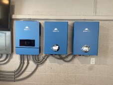
Install and Operation of the SUNGOLD 10KW 48V SPLIT PHASE SOLAR INVERTER

Wow! Excellent work there @Flatpicker !
Glad all is working out for you! Love those ground mounts!!
Thanks! I figure they probably won’t last too long, but I will pattern heavier, identical mounts in the near future. I can be pretty handy “gluing metal together” with a welder. Bought them for more of a “proof of concept” and they will be much heavier in 1/4” steel. Got a line on some more robust actuators too.
 
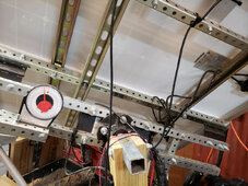
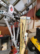
Nice Project. Just thought I would share. I have been futzing (technical term) with a solar tracking mount. Two 100 watt panels, 1 WitMotion WT901BLECL MPU9250 9 axis motion tracker, one GPS module, one wind speed sensor, one Renogy Wanderer charge controller and a small windows 10 computer with 10 inch touch screen to collect data from the charge controller, Witmotion and GSP modules. All parts purchased from Lowes and Northern Tool or Amazon. The linear actuators (from Amazon) are rated at 300lbs force and operate off 12vdc. The East/West pivot is a utility trailer axel hub mounted to the end of a utility trailer axel. I get 70 degrees (almost vertical) east to 70 degrees west motion and 5 degrees past north (horizontal) to 80 degrees south facing vertical.
I have a 6x6 piece of plywood with a 1 foot 3/4 inch dowel attached perpendicular in the center of the plywood (think sundial). I can set it on the face of the panels and the dowel casts less than 1/2 inch shadow which shows the tracker is pretty accurate. The whole shebang does nothing really, just was something to futz with. Since you seem capable of fabricating stuff I thought this might give you some ideas in building a single bigger tracker. The trailer hub is rated for 2000lbs and when you consider it going down the road at 55mph, it should have not problesn supporting a large array


Tracker1.jpgTracker3.jpg
 
Depends on how you are wiring it up. If 240 ac input then Black - L1, Red - L2, White - N
If you are only using 120 there is an alternate connection where Black feeds both L1 and L2 and White is N
take a look at the manual - you can download it before you purchase the system. It has the wiring/connection diagrams.

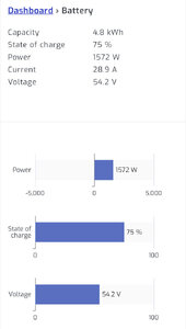
I think you'll love it if you don't rely on the Sungold wifi, best to replace it as I did with Solar Assistant....and as you probably know I'm still trying to work out the battery monitoring 'issues' but it's working fine batteries, charging, AC and all!

Good Choice of inverter in my mind!
I have been unable to figure out how to set up Solar Assistant, any tips?
 
I have been unable to figure out how to set up Solar Assistant, any tips?
Not sure what you are trying to figure out/set up. The Raspberry/Orange Pi just connects via USB cable to the inverter. You have to either purchase and download the software or buy the whole setup from Solar Assistant. If you want to connect directly to the batteries for monitoring directly see previous posts in this thread but will depend on whether you are using Sungold batteries or others.
 
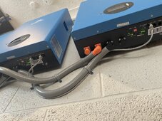
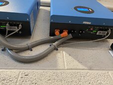
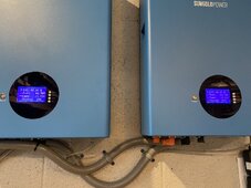
@Kenny_ ive got my second battery installed, I can’t find anything in the inverter showing it sees the second battery. I remember you talked about this. I don’t see it in solar assistant under battery. Am I looking in the wrong place? I’ve got dipswitch set to 2. Batt one is 1. Am i looking in wrong place of SA?

E862FC95-959F-4723-A932-768948EAAE2B.jpeg6B4F48B4-4E70-4FD7-A49E-B61598A00A6D.jpeg
 
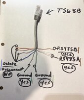
My 485 ports are correct right @Kenny_ ?
I built the cable like I did the other one from batts to inverter. Should I just use the cable in the box? I did this cable like Cindy instructed awhile back for inverter to batt

F3D56A44-077F-4541-A7AA-15580D230A13.jpeg5851B082-03F2-4F6E-BE99-C8604537F561.jpeg
 
Well...no...probably not.... you only have your SA/Raspberry connected to the inverter I presume?
It will show only what the Inverter shows on the screen... i.e. no indication of multiple packs/batteries.

Leave the comm from inverter to Battery exactly as you had it with the single battery.

Mine multiple battery/pack SA view only became apparent when I added a second connection from the Raspberry/SA to the battery directly via the rs232 console connection on battery #1. (i.e. see all that krap up above about my rs233 cable issues....only the cable from Sungold or Current Connected worked ... or build your own kinda)

---
From the photo you've plugged the battery to battery into the Rs485A port on the second battery this is wrong. (maybe)

Connect the Battery 1 RS485C to Battery 2 RS485B. Use the cable supplied with the battery for connecting battery 1 to battery 2. This is what is working for me.
So I’ve inverter to 485a on batt 1, then batt 1 485c to batt 2 485b.

I don’t have the SG wire to plug to SA directly,

I noticed my batt 1 is giving a lot more juice out

Still not sure if inverter knows it’s there

Guess I’m fine tho like this?

F61DB497-AE04-4D34-A3BA-A22670EAAB07.jpegF5198AD7-D340-446E-86D7-F93207F29787.jpeg
 
Shouldn't one of the inverter battery cables go to battery 1 and the other to battery 2?

As in positive cable for the inverter hooked to battery 1's positive and negative cable for the inverter hooked to battery 2's negative?
 
Shouldn't one of the inverter battery cables go to battery 1 and the other to battery 2?

As in positive cable for the inverter hooked to battery 1's positive and negative cable for the inverter hooked to battery 2's negative?
That all should be correct. The batts basically bridge the terminals inside the battery box. I talked to @42OhmsPA about this. The connectors they include are teethed different between + and - so it’s idiot proof

You can see it in another users big setup here… no buss bar ?
 

Attachments

  • E016DFB4-98E2-4C6E-A5B1-9C3501B12355.jpeg
    E016DFB4-98E2-4C6E-A5B1-9C3501B12355.jpeg
    186.4 KB · Views: 72
Shouldn't one of the inverter battery cables go to battery 1 and the other to battery 2?

As in positive cable for the inverter hooked to battery 1's positive and negative cable for the inverter hooked to battery 2's negative?
That's how I'd do it for a more equal current flow.

Currents should equal out once SOC equalizes.

Next up is the joy of building your own pack...
 
That all should be correct. The batts basically bridge the terminals inside the battery box. I talked to @42OhmsPA about this. The connectors they include are teethed different between + and - so it’s idiot proof

You can see it in another users big setup here… no buss bar ?
Its not what will go its how the power flows to keep it even.

Inverter positive > battery 1 1st positive

Inverter negative > battery 2 1st negative.

battery 1 2nd positive > battery 2 2nd positive

battery 1 2nd negative > battery 2 2nd negative

With your cables inside the covers I can't see how its actually wired it why I was mentioning it.
 
That all should be correct. The batts basically bridge the terminals inside the battery box. I talked to @42OhmsPA about this. The connectors they include are teethed different between + and - so it’s idiot proof

You can see it in another users big setup here… no buss bar ?

e016dfb4-98e2-4c6e-a5b1-9c3501b12355-jpeg.186543


I know on a lead acid setup that wiring will cause that last battery to be out of whack charge wise vs the others.
 
e016dfb4-98e2-4c6e-a5b1-9c3501b12355-jpeg.186543


I know on a lead acid setup that wiring will cause that last battery to be out of whack charge wise vs the others.
That picture is confusing because they have 2 inverters. I would have ran the batteries to a main bus...

Edit - I can't see... I would not have wired that way.
 
Last edited:
Shouldn't one of the inverter battery cables go to battery 1 and the other to battery 2?

As in positive cable for the inverter hooked to battery 1's positive and negative cable for the inverter hooked to battery 2's negative?
Kenny is that how yours are? From batt 1 positive post to inverter and negative cable from last battery to a nverter?

I know with led and stuff to draw like that but I guess that’s the same for these too maybe I should make my negative from batt 2 feed the inverter?
 
So I’ll disconnect that ground from batt1 to inverter and I’ll leave everything else as is. I’ll add this plug to batt 2s ground and run it into the inverter ground stud?

Correct?

CF4B6306-6460-4E7A-8FA1-CA6521FA9F91.jpeg
E139B0BD-39B1-4281-8BBA-76EE922A3FA5.jpeg
 
It looks like this dude did it like how mine is but they combine at a bussbar

I understand what you mean about drawing across the entire pack setup. I’m familiar with that being the correct method.

I guess I just looked over that concept as I assumed batt 1 was basically acting like a bussbar
65D5E880-72B3-43CD-8D19-A8F2DC8313A1.png
 
Kenny is that how yours are? From batt 1 positive post to inverter and negative cable from last battery to a nverter?

I know with led and stuff to draw like that but I guess that’s the same for these too maybe I should make my negative from batt 2 feed the inverter?
Yes... Diagonal. Inverter + to battery 1 .. Inverter - to battery 5.
 

diy solar

diy solar
Back
Top