diy solar

diy solar

JK BMS CAN bus comms now possible for inverters that support Goodwe and Pylontech batteries

If we're giving credit, let's give credit where credit is due.
Agreed

As an open source supporter, I am quite disappointed with the direction of the project. However, I respect uksa007's decision, for whatever reason that may be, and am thankful this was provided openly at all. Supporting an open source project takes a lot of work, and at some point, it's a personal decision to figure out how to pay the bills.
(y)
 
Edit confirmed from another source this is what you need:

Alpha ESS SMILE5-BAT Quick Installation Manual page 6

Suggests the following, should be similar for your inverter

View attachment 143876
On means switch UP, DIP 2 and 3 ON labels are wrong.
Do you think this would work with an Alpha ESS M48112-s battery
The inverter has failed and i am not happy with the alpha ESS T50 inverter
I would like ti know if i could get a goodwe or Deye 3 phase 50 kilowatt inverter to work with these batteries ?
I have 2 x 8 batteries
2 rack stacks
Each stack of 8 batteries is conected to the inverter DC Battery terminals via a HV 900 unit
Each HV-900 unit is connected via in-out daisy chain RS-485 to a BMS EMS box which also connects to the inverter via RJ45
so i suspect the dip switch settings would need to be assigned correctly?
Any help would be appreciated
 
Meh open source = open wounds.

Been there done that seen too many fights and drama.

Closed sourced, fairly price, with proper support wins in my opinion.

All those wanting open source have no idea on what do with it they just like the way it sounds. All they do is bug the original developer and ask, plead, and then demand changes all for free.

No thanks.
I'm sorry, but this is not at all how the open source model works. Open source developers are free to provide as much, or as little contribution to a project as they see fit. Send over a pull request to fix 1 typo? That's fine. Dedicate 8 hours of personal time per day to build entire new features and respond to community "demands"? Their own choice. The point is, contribute whatever you can, with the goal of forward progress. Heck, you don't even have to contribute anything, leeching off the contributions of others is totally fine too.

If you decide to write a valuable piece software from scratch and keep it closed source, more power to you. There is absolutely nothing wrong with that. However, the main point for this particular project is that it *would not exist* if it wasn't built on top of other open source projects, at least from the last state we can publicly see.

Source: Am a "closed source" developer, also leveraging numerous open source projects.
 
So your interface will not work with the JK + Phocos combination?
I mean both JK and Phocos have the RS485 interface.
Are you using CAN over RS485?

Hello, if interested in JK-BMS communication with Voltronic and clone inverters, I developed a YAML file for EspHome implementing Soltaro CAN protocol.
Started from syssi work (I connect to BMS via Bluetooth), I added a CAN device and implemented in YAML CAN protocol (based on Coulomb specifications).

And is open-source

jk-bms-soltaro.yaml

1702479956791.png
 
Last edited:
Hello, if interested in JK-BMS communication with Voltronic and clone inverters, I developed a YAML file for EspHome implementing Soltaro CAN protocol.
Started from syssi work (I connect to BMS via Bluetooth), I added a CAN device and implemented in YAML CAN protocol (based on Coulomb specifications).

And is open-source

jk-bms-soltaro.yaml

View attachment 182644

Thank you and long live sharing and open-source.

I also just wrote an ESPhome integration for a Junctek Shunt that I will share with the community when it is finished.
 
I adapted the YAML from version 1.13.3 of uksa007 by adding new functions.

I can explain how it works in detail later.

The repository on github : https://github.com/Sleeper85/esphome-jk-bms-can

The necessary components come exclusively from the syssi github : https://github.com/syssi/esphome-jk-bms

Below is the changelog:

# V1.15.1 Sleeper85 : New CANBUS script with CANBUS Status in HA, stop sending CAN messages if the inverter is not responding (fix WDT reboot issues).
# V1.14.3 Sleeper85 : Improved documentation + Charging Voltage tips for Deye
# V1.14.2 Sleeper85 : Improve 'Charging Voltage' behavior
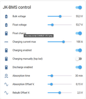
# V1.14.1 Sleeper85 : Add 'Float charge function'
# V1.13.6 Sleeper85 : Add 'Absorption time' and 'Absorption Offset V.' slider
# V1.13.5 Sleeper85 : Set CAN manufacter to "PYLON" for improve compatibility with Deye and other inverters
# V1.13.4 Sleeper85 : Improve 'Charge Status' behavior + add 'Rebulk Offset V.' slider
# V1.13.3 uksa007 : Improve compatibility with Deye and other inverters
# V1.13.2 uksa007 : Send Max Temperature of T1, T2 to inverter
# V1.13.1 uksa007 : Fix compile issues with new version of ESPhome 2023.4.0, set rebulk offset to 2.5


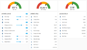
HA_Dashboard.png


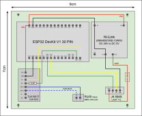
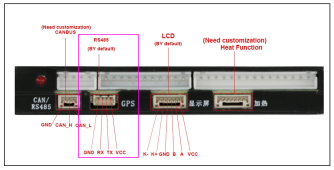
For those who wish to make their own board, here is the diagram of a board powered directly by the GPS port of the JK-BMS.

PCB - ESP32 JK-BMS CAN BUS V2.png


JK-BMS_24S_GPS_port.png
 
Last edited:
I adapted the YAML from version 1.13.3 of uksa007 by adding new functions.

I can explain how it works in detail later.

The necessary components come exclusively from the syssi github ( https://github.com/syssi/esphome-jk-bms ).

You will find the YAML attached.

Below is the changelog:

# V1.14.0 Sleeper85 : Add float charge function
# V1.13.6 Sleeper85 : Add 'Absorption time' and 'Absorption Offset V.' slider
# V1.13.5 Sleeper85 : Set CAN manufacter to "PYLON" for improve compatibility with Deye and other inverters
# V1.13.4 Sleeper85 : Improve 'Charge Status' behavior + add 'Rebulk Offset V.' slider
# V1.13.3 uksa007 : Improve compatibility with Deye and other inverters
# V1.13.2 uksa007 : Send Max Temperature of T1, T2 to inverter
# V1.13.1 uksa007 : Fix compile issues with new version of ESPhome 2023.4.0, set rebulk offset to 2.5
Now this is what open source is all about! Thank you for your contribution! Do you plan to fork the repo in github?

Also, it's great you have an isolated DC-DC converter module explicitly listed, fused appropriately on the input.

I mentioned this in another post, but as a reminder to those not extremely familiar with electronic design - please do not cheap out and use a non-isolated buck converter! Based on how they work, failure mode will cause voltage out == voltage in, which could potentially destroy your inverter if it ends up on the CAN lines!

Yes I'm thinking of putting this on github as well as another ESPHome integration for the Junctek KF-H shunt. ;)
 
Thank you for sharing it as open source

With pleasure, a next version 1.15 is coming soon with the correction of the main bug :

ESP32 has a bug that causes WDT reboot if no other devices on CAN bus to ACK the packets.
If you try to run without inverter it will not work as it will constantly WDT reboot!
 
Small Christmas gift.

The new version 1.15.1 is available on GitHub.

# V1.15.1 Sleeper85 : New CANBUS script with CANBUS Status in HA, stop sending CAN messages if the inverter is not responding (fix WDT reboot issues).

Stop sending CAN messages if no response (major improvement), code will detect when no inverter/not responding and stop sending CAN messages that resulted in WDT reboot issues. Code should now run without any issues if inverter is not connected.

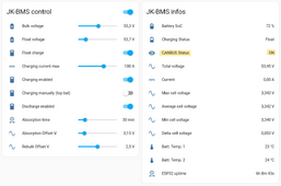
In addition, the CANBUS is monitored and you can see its status in Home-Assistant.

New CANBUS script 1.15.1.png
 
@Sleeper85

In a connection between bms and inverter, it is the bms which sends all the data present in the table below to the inverter.

Why with your system, is it user to register them?? The connection between the bms and the esp32 is useless in your case ??

Capture d’écran 2023-12-25 à 10.09.19.png
 
Last edited:
@Sleeper85

In a connection between bms and inverter, it is the bms which sends all the data present in the table below to the inverter.

Why with your system, is it user to register them?? The connection between the bms and the esp32 is useless in your case ??

Older JK-BMS does not communicate with the inverter. This application with ESP32 adds the missing layer of intelligence. All information is transmitted by the BMS via the ESP32 to the inverter but certain information such as charging voltage and current is information that does not exist in the BMS, so it's information that can be configured by the user via the YAML file or Home Assistant. It's in a way an extension of the BMS application adding the missing functions of a communicating BMS.
 
On the other hand, if you buy a new JK-BMS PB2A16S20P this application is useless and not compatible.
 
Back
Top