diy solar

diy solar

LIFEPO4 Smoke and Fire Dept

It doesn't look like the heat was generated by the bus bar connections. The terminals still look OK.
Doesn't seem like it should have shorted to the case if there was foam and the plastic wrap on the cell ..... not knowing what caused it is worse than making a mistake and causing it.

Edit .... after looking at that cell again, it does look like the top of the cell got pretty hot .... could have been a connection.
I have wondered on more that one occasion about the wisdom of brazing a stainless steel stud to an aluminum pad...(and no those posts are not welded, you cannot weld stainless and or any ferrous metal with aluminum in a true weld, best you can get is a brazed/soldered etc. joint)
 
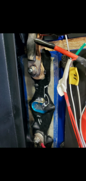
This photo shows there is some serious heat at the terminal, the plastic melted around the terminal. The terminal has also moved from it's original location on the busbar, you can see the witness mark on the busbar from it was originally installed. Note the discoloration of the busbar, some serious current had passed thru it. My honest opinion is the terminal had become loose causing the failure. I'm not sold on the multilayer busbars, at some point the layers move relative to one another and the result is loosening of the terminal. Stacked tolerance is that when assembling anything of multiple layers, there is a tolerance because materials differ in thickness on each layer. I prefer a single solid busbar with compression to eliminate any movement. Stacking will never end up perfect simply to to the busbar material having imperfections from when it was originally manufactured.

1663332308922.png
 
1 terminal badly tighten can get really really hot. its the only possibility i can think off. I had batteries i finished building and then run 100A+ through them, and then feel the busbars, if 1 of them is clearly warmer , is usually a connection there that isnt 100% tighten.
 
What is all the wiring for that is connected to the cells? Looks like some of them have at least 4 smaller gauge wires connected to it.

It also would be a lot safer if the wiring were organized in a cleaner fashion. Some of that wiring is pulled up underneath busbar connections, across busbars, etc. You should be able to look at the battery and tell what each wire is for and where it is going. Right now it looks like spaghetti.
 
Im racking my brain. Was/are they bad cells?
my BMS read around 3.3V on all cells. Even the cooked one ws 3.2V. After removing them all and checking with a meter the range is 3.27 to 3.31 per cell. resistance is between 2 and 4 megaohms. The cooked one is 6 megaphms and still has a voltage of 3.17v.

Mega or milli?
 
The case was over 200 degrees F. the cell above it was a little melted. possibly swollen. They all check out. my BMS read around 3.3V on all cells. Even the cooked one ws 3.2V. After removing them all and checking with a meter the range is 3.27 to 3.31 per cell. resistance is between 2 and 4 megaohms. The cooked one is 6 megaphms and still has a voltage of 3.17v.
Probably 1220F+. The cells should be between 0.15-0.25 milliohms or 2.5E-10 MΩ. If that is your 12kW Growatt, you need about 1200aH of battery or at least twice what you have. What is your max discharge amperage? I'm pushing 18000W out of two Sol-Ark 12K's with 2800aH. About 37A per battery. It will keep everything running cool and your cells will last longer. You may not even need those external balancers.
 
Last edited:
Is it even possible to have an IR that is in megaohms? Will it ignite if applied continuous current? Or current will not even flow?

Edit: "The skin contact resistance will usually be between 1000 and 100,000 Ω, depending on contact area, moisture, condition of the skin, and other factors. The skin thus provides most of the body's protection from electric current."
Skin res will vary from 1,000 Ohms to over 10 Mega Ohms. Mine presently is 8.5 Mega Ohms.
 
Last edited:
Hope you get it worked out. I’m convinced a power house is right for me. Not willing to take a chance.
For me on 10 batteries/2800aH...Power house 50' away from house, cooled to 70F, 40A charge/discharge max per battery, 2ga wiring rated for 115A, BMS's rated for 200A - set to 100A for 5 sec max, 100A 2p dc breaker, 125A class T between cell 8 & 9 to break battery in half, 1/4" ceramic fiber mat or "fiberfrax" between batteries and on ends, 1/4" cement board underneath batteries and covering exposed wood of battery shelf, behind inverters or any electrical components, 2 RF smoke detectors interconnected to 2 in house, 1 in work van (solar system too) and 1 in garage, 40 lb CO2 fire extinguisher, 100 lb halon extinguisher, 5 gallons of water, nomex racing gloves and balaclava.
 
Last edited:
The skin thus provides most of the body's protection from electric current."
I am still careful to not touch anything in a way that the current can flow from one hand to the other through my heart. The other thing to remember is some shocks may not kill you, but falling off a tall ladder or a roof can kill you.
 
Last edited:
After removing them all and checking with a meter the range is 3.27 to 3.31 per cell. resistance is between 2 and 4 megaohms. The cooked one is 6 megaphms and still has a voltage of 3.17v.

I was going to ask about BMS record of cell voltage balance, thinking charge to 3.375V/cell might not have triggered balancing. But 3.17V on bad cell indicates not over-discharged. I suppose over-charged and then self-discharged back within range isn't impossible.

But any over/under voltage of a cell ought to cause BMS to disconnect (does it have a disconnect mechanism?)
Bad connections of course are a source of voltage drop and heat. Could be considerable heat without voltage so far out of spec that BMS responds.
Busbars look like copper, but ends are grey - what is that? Copper on aluminum would be more likely to develop problems.

Compare temperatures of connections in remaining 15s battery after long period of high current. Check voltage drop from cell terminal to busbar (or cable terminal) under high current, no need to wait time for it to heat up before voltage drop appears.
 
just prompted me to recheck my battery and 1 terminal wasnt very well tight and the busbar was clearly hotter on that 1 terminal. I bet you had a similar issue. 1 loose terminal, lots of resistances, lots of heat, boom
 
I don't want to build my own batteries, time and hassle and all that, but I'm thinking it's a good idea to only get lifepo4s that have a bluetooth bms that shows cell data. Preferably with passive or active balancing.

I'm thinking if there is a cell that's frequently lagging behind the others, it's either bad or has a cruddy connection. Not much one could do about it in a sealed battery other than fight with the manufacturer, but at least you would know death is at your door.
active or passive balancing wouldnt save this problem. Its most likely a lose terminal. the BMS would never stop this unless it had a ton of temp sensors on every cell
 
Especially with aluminum battery terminals, CLEAN AND FLAT AND TREATED TO PREVENT OXIDATION is key.

Copper also have a mild oxidation layer, but it isn’t as bad as aluminum is.

30 seconds exposed to air, and aluminum forms an insulating layer. So all current would be flowing into the bussbar through the bolt.

Clean, and treat all terminals, and clean the copper plates as well.
 
active or passive balancing wouldnt save this problem. Its most likely a lose terminal. the BMS would never stop this unless it had a ton of temp sensors on every cell

Yeah, I meant I just want my BMS to have passive or active balancing, because I want it. The thing the bluetooth BMS would do in this situation is possibly allow me to see a cell that isn't charging as fast the others for whatever reason, possibly a loose/bad connection. Would have to watch it before it manages to balance it of course. If that cell then continues to do such things, you would know something is possibly up.
 
All cells in series will charge/discharge equally fast, because the only way current flows through one is to flow through the others (except for equalization.)
But voltage sensed by BMS can differ.
 
Back
Top