diy solar

diy solar

LV 6548's Split phase = Not Awesome

Stating that something is "not supported" without explaining the reason is what I expect from an offshore call center. Mpp solar and Signature solar did not engineer any of these. These are originally engineered by Voltronic Power Systems.
You must think I fell off the turnip truck yesterday.

If you were to actually go thru these forums and research what could be causing your problem, you might have found a solution. You came here instead to complain about your problem and wanted someone to I guess feel sorry for you.

I have a request into Voltronic for this issue to see what the real engineers have to say about my problem.
Good luck, it will come back as not supported.

The issues here are many, you most likely have the bonding screws still in the units along with a common neutral tied to the main service panel which also contains a N-G bond. Several parallel paths with objectionable current flowing everywhere.
 
One inverter popped when I first set them up. The problems started then. I think there was a problem with that was not on the main board. There is a possibility of a bad data cable. But that would not explain why they both popped when switching from SUB to BSU.
possibly a problem with one inverter and it’s started a reaction with the other. Hard to say.
 
The issues here are many, you most likely have the bonding screws still in the units along with a common neutral tied to the main service panel which also contains a N-G bond. Several parallel paths with objectionable current flowing everywhere.
If this is correct, then Ian needs to send me two new units because I setup the wiring exactly as he published on his websites.
 
@MPP Solar USA - Ian Roux is a good dude, but I feel his hands are tied with his support through MPP Solar. I've had so many issues with the MPP LVX6548 its simply not worth it. Would buy from Ian but never an MPP product ever again.
 
The inverters should be tested and operated with output Line, Neutral not connected to anything. Then each individually only connected to a load, not to each other.
It is possible the way the two are connected together shorts grid output, or has inverters fighting.

One guy wired Sunny Island with input and output both connected to grid, because they were in an out building and he wanted to power the house where service entrance panel was located. Output circuit breakers tripped without damaging it; maybe wire resistance limited current sufficiently. I explained that either wires should be run back from the battery inverter to a transfer switch, or the inverter located at the transfer switch. He wanted to keep it as it was, but dynamically switch relays so the wire run could be used bidirectionally. I never heard back if that was accomplished.


Several parallel paths with objectionable current flowing everywhere.

Perhaps, but what harm does "objectionable current" cause?

I have seen the expression used to refer to return current flowing in ground, when neutral is bonded to ground in more than one place. So a portion of the return current which was supposed to flow in neutral splits off to flow through ground, then back to neutral. Everything works, and you would likely be unaware of it.

I haven't thought of any way that connecting input neutral to output neutral would cause harm. The inverter itself does that for pass-through mode. Then it opens a relay connecting them and instead connects output neutral to ground. Whether or not neutral is hardwired to grid, what harm could that cause?


One inverter popped when I first set them up. The problems started then. I think there was a problem with that was not on the main board. There is a possibility of a bad data cable. But that would not explain why they both popped when switching from SUB to BSU.

Bad data cable or missing data cable could let the two inverters run independently. When on grid, each would just pass its phase of the grid through to output, and L1/L2 on output would look just like grid, no problem.

When off grid, each inverter would produce its L output unsynchronized with the other, so might be 240Vrms between them, then drift to zero, then back to 240Vrms. Output swings from zero to +170V to zero, switches H bridge, swings to -170V, and back. Possibly, after H bridge switches and an inverter is trying to pull output up to say +25V, if 240V load between that inverter and second inverter pulling output up to +170V, that pulls mosfet transistor source higher than gate, killing it.

But inverters need to be able to handle inductive and capacitive loads, which do just that.

If line and neutral were wired backwards, that would do funny things.
 
I haven't thought of any way that connecting input neutral to output neutral would cause harm. The inverter itself does that for pass-through mode. Then it opens a relay connecting them and instead connects output neutral to ground. Whether or not neutral is hardwired to grid, what harm could that cause?

Bad data cable or missing data cable could let the two inverters run independently. When on grid, each would just pass its phase of the grid through to output, and L1/L2 on output would look just like grid, no problem.

When off grid, each inverter would produce its L output unsynchronized with the other, so might be 240Vrms between them, then drift to zero, then back to 240Vrms. Output swings from zero to +170V to zero, switches H bridge, swings to -170V, and back. Possibly, after H bridge switches and an inverter is trying to pull output up to say +25V, if 240V load between that inverter and second inverter pulling output up to +170V, that pulls mosfet transistor source higher than gate, killing it.

But inverters need to be able to handle inductive and capacitive loads, which do just that.
Best reply I have seen yet!
 
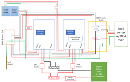
That diagram is from Ian's website. That is exactly how I set it up based on his website and the MPP manual. Besides, why would having both panels on the same neutral present a problem as long as the hots are not shared?

Current will flow on any parallel path whether it is a neutral or EGC, doesn't have to be a hot.

An example concerning neutral current and yes, this has happened to me. A long day, I was installing a 3 pole double throw and a subpanel. I was moving circuits from one panel to another next to it. Flipped off the breaker, disconnected the hot, disconnected the EGC and neutral, started to pull the neutral and EGC out and felt the buzz.

I had the wrong breaker and had lightly touched the open neutral. Luckily there was only the bedroom clock on that circuit so the current was minimal.

Both panels also share the same ground which is bonded with the neutrals anyway.

N-G bond in both panels? And bonding screws in the inverters, correct?
And, both inverters are also on the same ground.
 
Do you always get defensive and offensive when someone questions what you state
After reading a lot of this forum you'll get of feel of which ones to skip, sometimes even put on ignore. Arrogance, rather than avuncular behavior, abounds in some.
 
It appears you have N as common between both panels as shown at the top of the diagram. This is not supported, I guess you now know why.
@Zwy
Can you explain why that’s a problem? If G-N bond in main then L1, L2, N, G feeding a sub panel without the bond. Inverters L1, L2 on an interlock in sub panel along with G and N in sub panel.
 
I've been running split phase 240 on my two LV6548 inverters for about three months now with a light load. That's going to ramp up soon because I'm moving at least some of the AC over to it. Here's my drawing of how mine is wired. The only difference I see based on your drawing is possibly the grounding screws. I removed the screw in the second unit. I also have a three-pole double throw transfer switch but for the purposes of this discussion that should be irrelevant.


1677895957577.png
 
@Zwy
Can you explain why that’s a problem? If G-N bond in main then L1, L2, N, G feeding a sub panel without the bond.

Re-reading the posts, it appears the subpanel may have N-G bond also. The bonding screws may be in both inverters which would create N-G bond there under inverter power.
Inverters L1, L2 on an interlock in sub panel along with G and N in sub panel.
I'd prefer an answer by the original poster on whether N-G bond is in both panels and if bonding screws are in both inverters before commenting any further.
 
I've been running split phase 240 on my two LV6548 inverters for about three months now with a light load. That's going to ramp up soon because I'm moving at least some of the AC over to it. Here's my drawing of how mine is wired. The only difference I see based on your drawing is possibly the grounding screws. I removed the screw in the second unit. I also have a three-pole double throw transfer switch but for the purposes of this discussion that should be irrelevant.


View attachment 137820
You do not have common neutral. The 3 pole double throw switches neutral and the LV6548 transfer switch switches neutral. Your system is wired like mine, except I ran EGC from both inverters back to the main bonded panel only. The subpanel is right next to the main bonded panel and EGC runs between the panels, the inverters are 15 feet away.
 
So I have found some issues with the current, consensus on panel wiring. I have had no issues running 220. but i have had some observations and made some changes to how i wire the panel to handle said.. observations. DM and we can talk about it. not sure if I want to the forum coming down on my way of wiring.. if that makes sense.
 
You do not have common neutral. The 3 pole double throw switches neutral and the LV6548 transfer switch switches neutral. Your system is wired like mine, except I ran EGC from both inverters back to the main bonded panel only. The subpanel is right next to the main bonded panel and EGC runs between the panels, the inverters are 15 feet away.
I spent the extra money on the three-pole switch specifically to eliminate the common neutral issue. I know a lot of people use a common neutral and make it work but I wasn't willing to risk it. It may not be clear on my drawing but the only NG bond is in the main panel and everything is grounded back to the single earth ground at the main. I had a lot of help figuring this out but it seems to correct as far as I can tell.

I agree on getting a response from the OP on whether there are two NG bonds plus both screws being in place.

Grounding discussions give me a headache. :ROFLMAO:
 
I have also found that some motor driven appliances, like some wash machines, will switch to 3 phase in order to reverse the motor operation. Rather than do it with a transmission.This will kill an inverter too. I am trying to address this issue by replacing the appliance before the inverter.
But I am all about abusing my equipment, i bought it live off grid and use the stuff. though on the other building i am building I am thinking about a different system. we will see what pans out. but i can 240 tig weld. i am happy .
 
Re-reading the posts, it appears the subpanel may have N-G bond also. The bonding screws may be in both inverters which would create N-G bond there under inverter power.

I'd prefer an answer by the original poster on whether N-G bond is in both panels and if bonding screws are in both inverters before commenting any further.
You are correct, I never removed any screws from the LV6548's so I assume they still had the NG bond.
 
Back
Top