DerpsyDoodler
Solar Addict
- Joined
- Jan 10, 2021
- Messages
- 2,247
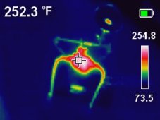
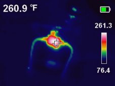
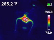
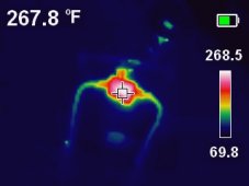
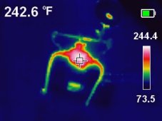
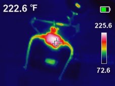
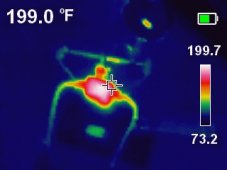
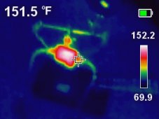
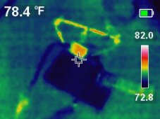
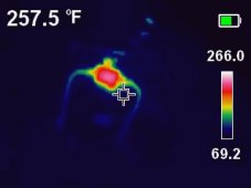
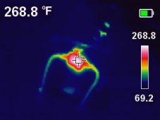
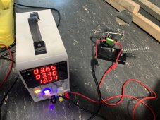
I bought some 1ohm 25 watt resistors (shown in the picture) to be able to individually drain high cells across a battery. Essentially a manual balancer. I soldered some copper wire to the ends and put some heat shrink over it. Works well. drains ~3a (as expected) while its connected. If i leave it on for more than 5 seconds it starts to get pretty hot.
My question is should it get hot? if the cell was fully charged it would be 3.65v, so i run the calcs with that.
3.65v * 1 ohm = 3.65a
3.65v * 3.65a = 13.32 watts.
13.3 watts is well under the 25 its rated for. Why does it get so hot? Is my understanding mistaken somewhere?
Since i have 5 of them, i could do 2s2p with the resistors and have the same current flow but the power loss spread across 4 resistors instead of just one. Would this prevent them from getting so hot so fast?
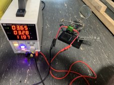
I did measure the resistance of the resistor (confirmed @ 1 ohm) and I also attached a clamp ammeter to the resistor circuit and i saw ~3.2a going through.
Ideally, i'd like to just be able to put this in place and hold it for 20-30 seconds without worrying about it.
Can anyone offer some insight as to why this isn't working the way I expected it to?

My question is should it get hot? if the cell was fully charged it would be 3.65v, so i run the calcs with that.
3.65v * 1 ohm = 3.65a
3.65v * 3.65a = 13.32 watts.
13.3 watts is well under the 25 its rated for. Why does it get so hot? Is my understanding mistaken somewhere?
Since i have 5 of them, i could do 2s2p with the resistors and have the same current flow but the power loss spread across 4 resistors instead of just one. Would this prevent them from getting so hot so fast?
I did measure the resistance of the resistor (confirmed @ 1 ohm) and I also attached a clamp ammeter to the resistor circuit and i saw ~3.2a going through.
Ideally, i'd like to just be able to put this in place and hold it for 20-30 seconds without worrying about it.
Can anyone offer some insight as to why this isn't working the way I expected it to?