Hi All
I currently have the following installed on my yacht
7.2 kW solar panels
44 kW Lifepo4 battery bank
10 kW invertor 230 V
18 kW genset
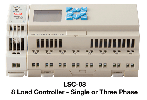
I would like to install some sort of automatic load control so that large power drawing equipment cannot operate simultaneously while on inverter power. Obviously I already have suitable circuit breakers installed on all circuits and thus when the loads are exceeded, the breakers trip (works, but is a pain). Ideally, I would prefer to simply deny power to other circuits when one of the large power draw items is operating.
300 l/h Water maker: 4 kW
3 x Water heaters: 3 kW
Gally (dishwasher/toaster/kettle): 4 kW
Induction hob: 5 kW
Oven & microwave: 4 kW
Obviously I could install a 5 position selector switch, but I'm hoping that somebody can recommend a more elegant ((automated) solution.
Many thanks
I currently have the following installed on my yacht
7.2 kW solar panels
44 kW Lifepo4 battery bank
10 kW invertor 230 V
18 kW genset
I would like to install some sort of automatic load control so that large power drawing equipment cannot operate simultaneously while on inverter power. Obviously I already have suitable circuit breakers installed on all circuits and thus when the loads are exceeded, the breakers trip (works, but is a pain). Ideally, I would prefer to simply deny power to other circuits when one of the large power draw items is operating.
300 l/h Water maker: 4 kW
3 x Water heaters: 3 kW
Gally (dishwasher/toaster/kettle): 4 kW
Induction hob: 5 kW
Oven & microwave: 4 kW
Obviously I could install a 5 position selector switch, but I'm hoping that somebody can recommend a more elegant ((automated) solution.
Many thanks