Please see attached diagram.
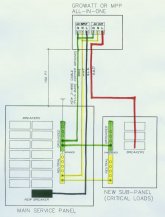
Main house panel is about 150ft to solar shed where Growatt or MPP single-phase all-in-one (off-grid) inverter will be housed below PV array.
Would prefer to run one 3-conductor (red/blk/wht plus bare copper ground) cable from main house panel to shed instead of two separate 2-conductor cables. Existing underground conduit has limited space.
At inverter: 'AC Input' lugs will receive Line (blk), Neutral (wht), and Ground (grn) feed from Main panel as normal, from new circuit breaker.
A new loads sub-panel will be installed right next to existing main panel. Sub-panel will be grounded to main panel ground and neutral busbar will connect to main panel neutral bus as shown. Sub-panel neutral bus will be unbonded from ground at the sub-panel. Main panel neutral is bonded to ground.
At inverter: 'AC Output' Line (red) will connect back to new sub-panel to power new loads breakers.
Ground (grn) will be jumpered from Ground at 'AC Input' lug as shown.
Neutral (wht) will be jumpered from Neutral at 'AC Input' lug as shown.
Question is...will this work or will my equipment get fried? Trying to avoid having to re-trench the long distance.