diy solar

diy solar

Need help understanding discharge amps

MartyByrde

Off-Grid Innovator
Joined
May 16, 2022
Messages
152
Location
USA
Hello,

I have four LiFePo4 280Ah 16s’ in parallel on a busbar. I’ve been disappointed in how they’ve been performing - I thought I would get greater battery life. I thought fully charged I’d be able to run a 4000w load for at least 10-12 hours. It basically has been lasting about 3-5 hours. Usually it’s at 52.5v at sundown.

I decided to do some testing with the multimeter.

Tonight I am running a smaller 600W load. It shows 16.8 amps discharging from the battery. My wall outlet plug shows only 6.45 amps being discharged from the 120v plug.

Why is there such a big difference in the amps being used?

Does this mean I need to assume my batteries capacity is a fraction of what I thought?

Even just typing this message, the 600w load has drained all four from 51.5v to 51.2v in the course of 30 minutes. Not sure if this is normal with the discharge curve. I’d expected more capacity with four 16s batteries.
 
My math might be wrong, bit it seems like it's working as expected.

280ah X 52.5v = 14,700wh

14,700wh / 4000w = 3.65h

Edit: I may have misread your description. Can you verify your battery arrangement?
 
Tonight I am running a smaller 600W load. It shows 16.8 amps discharging from the battery. My wall outlet plug shows only 6.45 amps being discharged from the 120v plug.

Don't confuse A/C current draw at 120V with the DC draw at nominal 48v your readings are correct.

As for your question, if you have16s4p all 280ah then you should have a 1120Ah pack in total or 53.7kWh pack capacity, either the cells aren't 280Ah, not wired correctly or they haven't got to full charge. What BMS are you using to manage 16s4p?
 
My math might be wrong, bit it seems like it's working as expected.

280ah X 52.5v = 14,700wh

14,700wh / 4000w = 3.65h

Edit: I may have misread your description. Can you verify your battery arrangement?
I have four though so I thought it was 1120ah x 52.5v?
 
Yes, not certain on the actual battery size. Do you have 16- 280Ah cells configured as one 48v (nominal) battery? This would be 51.2v x 280Ah = 14,336Wh. Close to what camelCase suggested, and would agree with his conclusion. Otherwise, 57.3kWh and 1120Ah... what shavemcspud said.
 
Don't confuse A/C current draw at 120V with the DC draw at nominal 48v your readings are correct.
Is there a formula/fraction for this that you are aware of to help going forward?
As for your question, if you have16s4p all 280ah then you should have a 1120Ah pack in total or 53.7kWh pack capacity, either the cells aren't 280Ah, not wired correctly or they haven't got to full charge. What BMS are you using to manage 16
Don't confuse A/C current draw at 120V with the DC draw at nominal 48v your readings are correct.
Appreciate you confirming. Is there a formula/fraction for this that you are aware of to help going forward?
As for your question, if you have16s4p all 280ah then you should have a 1120Ah pack in total or 53.7kWh pack capacity, either the cells aren't 280Ah, not wired correctly or they haven't got to full charge. What BMS are you using to manage 16s4p?
They’re wired on a busbar like this with +\- indicating wire attachment:

+abcd abcd-

>Cells are closely balanced. I am using overkill Solar BMS for three of the batteries and Daly BMS for one.

>Basically everything is controlled by the inverter. I have the bulk float and cut off set on the Inverter. Usually the BMS is not needed. If we hit low-voltage, the inverter powers off long before the BMS would. I have bulk at 55.4, float at 54.4, and cut off at 48. I recently just increased flow, because my growatt charge controllers would shut off around 12 o’clock noon. It was recommended that I slowly increase the float, and change from USE2 to USE.

Are we really that early to solar?!?! Lol
 
It looks like your multimeter readings are close to correct for the 600w load, but you are comparing DC to AC, and there is loss in the conversion from DC to AC depending on the efficiency of your inverter.
 
Is there a formula/fraction for this that you are aware of to help going forward?


Appreciate you confirming. Is there a formula/fraction for this that you are aware of to help going forward?

They’re wired on a busbar like this with +\- indicating wire attachment:

+abcd abcd-

>Cells are closely balanced. I am using overkill Solar BMS for three of the batteries and Daly BMS for one.

>Basically everything is controlled by the inverter. I have the bulk float and cut off set on the Inverter. Usually the BMS is not needed. If we hit low-voltage, the inverter powers off long before the BMS would. I have bulk at 55.4, float at 54.4, and cut off at 48. I recently just increased flow, because my growatt charge controllers would shut off around 12 o’clock noon. It was recommended that I slowly increase the float, and change from USE2 to USE.

Are we really that early to solar?!?! Lol

Is there a formula/fraction for this that you are aware of to help going forward?
Yes watts divided by voltage 600watts / 48V DC nominal = 12.6Amps DC
600 watts / 110v A/C = 5.5Amps A/C

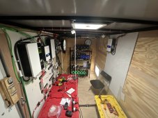
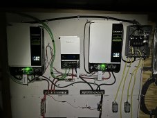
Think we need a photo of the setup to clarify whats going on
 
Looks like everything is working as it should be.
Other than not getting the expected capacity.
This could be due to not getting a full charge. Or lower quality cells. Do you have a shunt connected? This is the only way to find out.
 
I have bulk at 55.4, float at 54.4, and cut off at 48.
There is a GOTCHA you haven't accounted for.
1) The kWh formula = 3.200 (nominal cell voltage) X 16 Cells = 51.2V (nominal pack V) X 280AH = 14.336 kWh
--> 3.200Vpc = 50% SOC as it is dead center of the Working Voltage Range of 3.000-3.400

2) Bulk @ 55.4V (3.462Vpc) will get the packs to slightly above the Working Range but NOT Saturated to that point.

3) Float @ 54.4V (3.400Vpc) will only saturate the cells to that voltage WHEN the battery is only taking <14A or lower (better).

4*) Once any charge stops LFP settles (it is the chemistry & normal) this is usually 0.5-1.0 Volts per pack ! That translates to 53.9V (3.368Vpc) - 53.4V (3.337Vpc) within the pack. This depends on the grade of cells, their internal resistance and what balancing is going on by BMS.

Change FLOAT to 55.3V (3.456Vpc) which will allow for the batteries to settle @ 54.3 (3.393Vpc) giving you the top of working range.
Adjust your ABSORB to 120 minutes. Average is 10 Minutes per 100AH capacity. Most often it will not run that long as EndAmps/Tailcurrent will be reached kicking absorb to Float. Your EndAmps is 14A

An important side note: If one battery is "weaker" than the rest it will draw down to the Lowest Common Denominator within the Bank. A single cell within a pack can also result in a drawdown of that pack and then the rest within the bank. For example, if you have a pack with one cell that will not reach 3.400V say it's 3.370 and the other cells go higher to compensate while charging to have the pack at 55.3V, the moment Float stops, it will draw down the pack regardless of the type of balancing (worse with Passive Balancing as that only discharges higher cells). Active Balancing will try to transfer from higher cells to the lower cells and float will cover that with a trickle input while Float is active & capable. BUT the moment you transition from active Float to discharge only, the draw down will occur. * This is why Matched & Batched cells that keep an identical IR throughout the Working Range of 3.000-3.400 make the difference, any cell that is outside of the matching IR range WILL affect the entire pack negatively. The lowest common denominator will always rule the pack, it is the handi capper of the pack and subsequently the bank overall.

Also you need to ensure that all the BMS' have identically matched settings and that they are voltage calibrated to match "Actual Pack Voltages" at the (+) & (-) take off points (B- & B+) sense leads, NOT at the terminals where the big cables are attached. Then you also need to calibrate your gear (SCC's & Inverter/Chargers) so they correct/compensate for ANY Line Losses between the banks Common DC Bus.

Lastly, Inversion Innefficencies (losses) also need to be taken into account when going from DC to AC as there is anywhere from 5% to 20% losses depending on the grade & quality of the inverters. IE cheapo Value Inverter/chargers can be as low as 85% efficient while Top Grade Tier-1 products can be 95% efficient.

!*!: When Calibrating a BMS, you MUST turn off Charge, Discharge & Balancing, the battery cells must be Static to get a "clean" read with a high quality DMM/DVOM which is at least 2 Decimal Point Accurate. Remember to ZERO the DMM by touching the the two leads together before taking a reading. Some DMM's are so sensitive they pickup electrical flow off the wires which you will see as fluctuating low voltage readings, you may have to turn off the SCC's & inverters etc while calibrating the BMS' to get a good clean read.

Hope it helps, Good Luck.
Steve
 
Last edited:
Usually it’s at 52.5v at sundown.

Even just typing this message, the 600w load has drained all four from 51.5v to 51.2v in the course of 30 minutes.

52.5v / 16 = 3.29v average voltage per cell. Under load current that would be greater than 50% state of charge. If cells are out of balance some cells will be greater voltage, some will be less. The lowest out of balance cell voltage could trip low voltage shutdown on BMS.

Total discharge would be in the range of 2.75v x 16 = 44 vdc.

Theoretical capacity is 4 x 280AH x 50.5v = 56.2 kWH's.
Multiply by system conversion efficiency, assume about 90%,
56 kWH * 0.9 = 50 kWH.

Most common reasons for not getting capacity expected:

1) cells out of balance

2) not fully charging battery

3) too much battery cabling voltage drop.

4) Poor condition, used cells

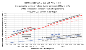
Dropping from 51.5v to 51.2v under 600 watt load (<12 amp draw on battery with inverter idle overhead) is 0.3v drop / 16 = 19 mV average overpotential voltage slump per cell. This is very normal for < 12 amp load on 280 AH battery.
LF280 overpotiential curve.png
 
Last edited:
52.5v / 16 = 3.29v average voltage per cell. Under load current that would be greater than 50% state of charge. If cells are out of balance some cells will be greater voltage, some will be less. The lowest out of balance cell voltage could trip low voltage shutdown on BMS.

Total discharge would be in the range of 2.75v x 16 = 44 vdc.

Theoretical capacity is 4 x 280AH x 50.5v = 56.2 kWH's.
Multiply by system conversion efficiency, assume about 90%,
56 kWH * 0.9 = 50 kWH.

Most common reasons for not getting capacity expected:

1) cells out of balance

2) not fully charging battery

3) too much battery cabling voltage drop.

4) Poor condition, used cells

Dropping from 51.5v to 51.2v under 600 watt load (<12 amp draw on battery with inverter idle overhead) is 0.3v drop / 16 = 19 mV average overpotential voltage slump per cell. This is very normal for < 12 amp load on 280 AH battery.
View attachment 120601
Thanks for this explanation. I believe this was the result of one or two cells being out of balance. After your post, I really went back and looked at each BMS and found the new battery I added was still balancing. The cells have balanced now and it’s functioning much better.
 
There is a GOTCHA you haven't accounted for.
1) The kWh formula = 3.200 (nominal cell voltage) X 16 Cells = 51.2V (nominal pack V) X 280AH = 14.336 kWh
--> 3.200Vpc = 50% SOC as it is dead center of the Working Voltage Range of 3.000-3.400

2) Bulk @ 55.4V (3.462Vpc) will get the packs to slightly above the Working Range but NOT Saturated to that point.

3) Float @ 54.4V (3.400Vpc) will only saturate the cells to that voltage WHEN the battery is only taking <14A or lower (better).

4*) Once any charge stops LFP settles (it is the chemistry & normal) this is usually 0.5-1.0 Volts per pack ! That translates to 53.9V (3.368Vpc) - 53.4V (3.337Vpc) within the pack. This depends on the grade of cells, their internal resistance and what balancing is going on by BMS.

Change FLOAT to 55.3V (3.456Vpc) which will allow for the batteries to settle @ 54.3 (3.393Vpc) giving you the top of working range.
Adjust your ABSORB to 120 minutes. Average is 10 Minutes per 100AH capacity. Most often it will not run that long as EndAmps/Tailcurrent will be reached kicking absorb to Float. Your EndAmps is 14A

An important side note: If one battery is "weaker" than the rest it will draw down to the Lowest Common Denominator within the Bank. A single cell within a pack can also result in a drawdown of that pack and then the rest within the bank. For example, if you have a pack with one cell that will not reach 3.400V say it's 3.370 and the other cells go higher to compensate while charging to have the pack at 55.3V, the moment Float stops, it will draw down the pack regardless of the type of balancing (worse with Passive Balancing as that only discharges higher cells). Active Balancing will try to transfer from higher cells to the lower cells and float will cover that with a trickle input while Float is active & capable. BUT the moment you transition from active Float to discharge only, the draw down will occur. * This is why Matched & Batched cells that keep an identical IR throughout the Working Range of 3.000-3.400 make the difference, any cell that is outside of the matching IR range WILL affect the entire pack negatively. The lowest common denominator will always rule the pack, it is the handi capper of the pack and subsequently the bank overall.

Also you need to ensure that all the BMS' have identically matched settings and that they are voltage calibrated to match "Actual Pack Voltages" at the (+) & (-) take off points (B- & B+) sense leads, NOT at the terminals where the big cables are attached. Then you also need to calibrate your gear (SCC's & Inverter/Chargers) so they correct/compensate for ANY Line Losses between the banks Common DC Bus.

Lastly, Inversion Innefficencies (losses) also need to be taken into account when going from DC to AC as there is anywhere from 5% to 20% losses depending on the grade & quality of the inverters. IE cheapo Value Inverter/chargers can be as low as 85% efficient while Top Grade Tier-1 products can be 95% efficient.

!*!: When Calibrating a BMS, you MUST turn off Charge, Discharge & Balancing, the battery cells must be Static to get a "clean" read with a high quality DMM/DVOM which is at least 2 Decimal Point Accurate. Remember to ZERO the DMM by touching the the two leads together before taking a reading. Some DMM's are so sensitive they pickup electrical flow off the wires which you will see as fluctuating low voltage readings, you may have to turn off the SCC's & inverters etc while calibrating the BMS' to get a good clean read.

Hope it helps, Good Luck.
Steve
All of the batteries are connected to a bus bar in parallel. The cables connecting each battery pack to the busbar are different lengths, would this make an impact?
 
All of the batteries are connected to a bus bar in parallel. The cables connecting each battery pack to the busbar are different lengths, would this make an impact?
It is possible depending on wire lengths and also if the (+)&(-) wires are of different lengths as well. A couple of centimeters won't matter much but the greater the difference the greater the potential.

Thing is, unlike Lead Acid (brute force tech) any Lithium based chemistry is NOT "brute force" and these are Millivolt & Milliohm sensitive so "little things" matter especially when they pile up and it does not take long. Even different wire types, for example Ultra Fine strand copper wire versus coarse stranded copper wire can make quite a difference. Every lug, crimp, solder connection, switch, relay, breaker or fuse adds resistance & some loss "on the wire" and while each one may be minimal, tally up the lot and could be 1 or 2 volts in time. Even how you connect to Common DC Busbars can make quite a difference.

Example busbar connections:
[ (B1+) , (B2+), (B3+), B4+), (B+<->) ]
[ (B1-) , (B2-), (B3-), B4-), (B-<->) ]
most folks do it something like this above and IT IS FINE but they may wonder why B4 gets more juice while charging and more load when discharging.

[ (B4+) , (B3+), (B2+), B1+), (B+<->) ]
[ (B1-) , (B2-), (B3-), B4-), (B-<->) ]
BUT switch it so that the + & - are opposite and the picture changes a bit... ! Some cases can be significant while others not much, depends on the batteries & the quality of the components too.

Then you have some folks swear by this method:
[ (B4+) , (B3+), (B+<->), (B2+), B1+) ]
[ (B1-) , (B2-), , (B-<->). (B3-), B4-) ]
and they get to see yet a different result

NB where (B?<->) = in/out to Inverter/scc circuit

Hope it helps, Good Luck.
 
I would advise putting a coulomb meter on each set of banks. They will tell you the exact SOC & if the voltages drop is well below it's expected discharge rate, then you have some weak batteries. A lot of these so called grade A sellers are pawning off near end of life cells that'll seem ok at 1st but degrade fast.
 
Looks like everything is working as it should be.
Other than not getting the expected capacity.
This could be due to not getting a full charge. Or lower quality cells. Do you have a shunt connected? This is the only way to find out.
Yes it wasn’t fully charged. Victron smart shunt helped a lot
 
Is there a formula/fraction for this that you are aware of to help going forward?
Yes watts divided by voltage 600watts / 48V DC nominal = 12.6Amps DC
600 watts / 110v A/C = 5.5Amps A/C

Think we need a photo of the setup to clarify whats going on
 

Attachments

  • 87CF3C38-5912-41A5-AF81-4983E8031B4B.jpeg
    87CF3C38-5912-41A5-AF81-4983E8031B4B.jpeg
    231 KB · Views: 13
  • 5E543ED0-94DE-4E45-8F9C-32AE2E7B0977.jpeg
    5E543ED0-94DE-4E45-8F9C-32AE2E7B0977.jpeg
    420.2 KB · Views: 13
Back
Top