Here's an ESA bulletin with some info:Ah interesting. So I might be able to push back on this then.


You are using an out of date browser. It may not display this or other websites correctly.
You should upgrade or use an alternative browser.
You should upgrade or use an alternative browser.
Need To Add Arc Fault Detection to system
- Thread starter lws2036
- Start date
Hedges
I See Electromagnetic Fields!
- Joined
- Mar 28, 2020
- Messages
- 20,680
Also I think RSD is probably underrated for reducing risk when servicing your own DC system.
I was going to say transistors and control circuitry didn't seem sufficient for human safety, but realized Rapid Shut Down to avoid exposing firemen to HV DC is exactly that. Normally, we would want a UL listed disconnect (1" gap?) not just a toggle switch or "supplemental protector".
I would say treat the lines as hot, hazardous anyway. They probably only deliver 0.7V to 1.0V per panel in series while shut down, but handle the wires as if 600Voc or whatever (disconnect MC before putting screwdriver on terminals) just in case they wake up or malfunction.
" PV source and output circuits " - the output circuits I assume to be charger controllers and inverter, which I do have in a small building. So I guess the question is, do both have to be on a building to require arc? If the output circuits are in a building, does this trigger the arc requirement? My ESA inspector seems to think yesHere's an ESA bulletin with some info:
zanydroid
Solar Wizard
Yes, it is in addition to a disconnect switch. Disconnect switch will not do anything about high voltage within the array.I was going to say transistors and control circuitry didn't seem sufficient for human safety, but realized Rapid Shut Down to avoid exposing firemen to HV DC is exactly that. Normally, we would want a UL listed disconnect (1" gap?) not just a toggle switch or "supplemental protector".
Array level RSD will not really do much more than a physical disconnect.
The wires should still be treated as live.
Trip.Diamond
New Member
- Joined
- Nov 15, 2021
- Messages
- 36
They are on a separate rack, my issues is the structure I made to house the batteries and solar equipment is large enough to be considered a building. According to my inspector, this is enough to warrant needing arc fault.
I would tread very carefully when questioning your AHJ but with that said, if your not using the building for anything other then housing the solar equipment, you shouldn't need arc-fault protection. Unless you have a local ordinance that says different. The NEC does not have a size limit for the solar shed. Only that it can't be used for any other purpose.
https://iaeimagazine.org/columns/ph...safety-requirements-for-photovoltaic-systems/
with a pertinent part being:

The OP is dealing with the Canadian Electrical Code, which is often similar and often very different from the NEC.I would tread very carefully when questioning your AHJ but with that said, if your not using the building for anything other then housing the solar equipment, you shouldn't need arc-fault protection. Unless you have a local ordinance that says different. The NEC does not have a size limit for the solar shed. Only that it can't be used for any other purpose.
https://iaeimagazine.org/columns/ph...safety-requirements-for-photovoltaic-systems/
with a pertinent part being:
View attachment 144244
The PV source circuits are the wires between panels and from panels to combiner boxes. PV output circuits are the wires from combiner boxes to charge controllers. This pic is NEC-based but I believe the NEC and CEC crossover here." PV source and output circuits " - the output circuits I assume to be charger controllers and inverter, which I do have in a small building. So I guess the question is, do both have to be on a building to require arc? If the output circuits are in a building, does this trigger the arc requirement? My ESA inspector seems to think yes
zanydroid
Solar Wizard
What is it that makes having panels vs just the last homerun riskier to the point of needing arc fault? More wires of lest robust wiring method when panels are there?But does the structure housing the equipment have the panels, or are they still on a separate rack? Because just housing the equipment without panels doesn't require arc fault. The arc fault requirement kicks in when the building has panels on it.
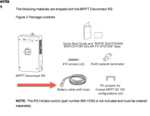
I am not able to find the power cable that came with this Schneider disconnect unit. It looks like that attached diagram. I posted a question on Amazon about getting a replacement, and got the following answer from Schneider:
I'm having some issues picturing what they want me to do. Does someone here have any tips or guidance?
I'm having some issues picturing what they want me to do. Does someone here have any tips or guidance?
Attachments
zanydroid
Solar Wizard
They’re saying make your own cable.
Instructions seem incomplete because it doesn’t talk about all the connectors you need.
What is the power for? IE what is the job of this in system block diagram.
Instructions seem incomplete because it doesn’t talk about all the connectors you need.
What is the power for? IE what is the job of this in system block diagram.
You don't need anything fancy. Pins 1 and 2 will get wired to your battery. Just about any 2 conductor cord will do, since it's fused at only 2 amps. Personally, I wouldn't use anything smaller than 18 gauge.
The manual I found online says Pin1 goes to the negative connector on your battery, and Pin2 goes to the positive connector of your battery with a 2 amp fuse inline.
However, the sticker in your box seems to show it just the reverse. Positive to Pin 1, Negative to Pin 2. I would go with what the box says.
Make sure the polarity is correct before powering it. Damage is likely to occur if it's backwards.
BTW, you may need to put a jumper wire between pins 3 and 4 to simulate the RSD switch. I would try it first without it, but if you get the Red RSD light indicating an RSD fault, that's probably why.
I'm no expert, but I think you're on the right track. The wiring between panels isn't in conduit. Sustained arcing faults have led to several roof top fires. I guess an arc contained in a conduit or metal box is far less likely to be a problem.What is it that makes having panels vs just the last homerun riskier to the point of needing arc fault? More wires of lest robust wiring method when panels are there?
So you were right. I did get this hooked up using the labeling on the box. I got the lights, and like you predicted I got the blinking RSD light. But also as predicted in this thread, this unit will not disconnect if an arc fault happen without changing my MPPT controllers to Schneider ones. Looking at trying this: https://www.solarflexion.com/product-p/icsplus-2.htmYou don't need anything fancy. Pins 1 and 2 will get wired to your battery. Just about any 2 conductor cord will do, since it's fused at only 2 amps. Personally, I wouldn't use anything smaller than 18 gauge.
The manual I found online says Pin1 goes to the negative connector on your battery, and Pin2 goes to the positive connector of your battery with a 2 amp fuse inline.
However, the sticker in your box seems to show it just the reverse. Positive to Pin 1, Negative to Pin 2. I would go with what the box says.
Make sure the polarity is correct before powering it. Damage is likely to occur if it's backwards.
BTW, you may need to put a jumper wire between pins 3 and 4 to simulate the RSD switch. I would try it first without it, but if you get the Red RSD light indicating an RSD fault, that's probably why.
Last edited:
Similar threads
- Replies
- 37
- Views
- 989
- Replies
- 1
- Views
- 197
- Replies
- 5
- Views
- 411
- Replies
- 52
- Views
- 3K