FilterGuy
Solar Engineering Consultant - EG4 and Consumers
Did you ever get it all working?


I'll check. I am also wondering how to set the input voltage. I have a pure sine Giandel unit 4000w to 8000 peak. I came home after one of the first sunny days and the thing was buzzing like a high pitch constant beep. I check the manual and it said "Inverter is in over voltage protection" I dont see in the instructions how to set thatI found the manual for the ATS and it says this:
View attachment 33172
Is the output Neutral floating? (Stick a voltmeter between ground and neutral... if you see a voltage, it is floating). If so, that is a rather dangerous unit. If you get a short from hot to equipment ground the breaker won't pop. The only time the breaker will pop is a short between hot and Neutral.
That little diagram of yours has led me to believe that I may have gotten some of my L and N wires reveres with respect to the other AC inputs on my switch. So the question I have is what happens if I have the L and N wires on my wall power correct but the wires are reversed coming from my inverter? My unit is acting seriously odd. I double checked the wiring to make sure my inverter output is going to the inverter input and the same for house power, but.....when the switch box told me it was getting power from the batteries, it was actually getting it from the the house and so my quick fix was to simply take the inverter out to the house in and vice versa and the unit began working right, but when I woke this morning the switch now showing that the switch was set to house (battery had dropped below the switch point) but was still using the inverter power and so I switched it back again. Very odd. Oh, and I do not have the set up grounded, just using line and neutral from both my wall and inverter outputs.Reading the doc, and trying to understand, they show 2 here: like supports both 120v in a 5500w configuration, or 240v in a 11000w configuration:
However top picture shows L N while bottom picture shows L L for public power in. This might make it seem to me like they are 2 different unit model numbers (unless they ship this unit with 2 stickers)..
View attachment 27997
Anyways, check your inverter output voltage and report back on that, this will help us decide which voltage you need to use for sure to make this work right.
Fix that so the color conventions are correct.So the question I have is what happens if I have the L and N wires on my wall power correct but the wires are reversed coming from my inverter
My set up does not allow for color conventions as they are cheap extension cords. In this case the plastic is brown. The only way I could figure out what was line and neutral is look them up on the internet and I possibly learned that the ribbed side of the wires is neutral and that is the larger of the two prongs. But...when I said I checked my connections, I just checked to see if the inverter was going into the inverter and vice versa for the house power. But your advice is probably correct whether or not I use color or ribs or checky, checky to make sure they are at least wired right with respect to each other. But hell, if I am going to do that, I might as well do it right. I will post back most tic. Edit: I just checked and all the ribbed side of the power cords are all on neutral and since all the outlets are keyed so they can't be reversed at the outlet, I am assuming that my wiring is correct. The sun is out and my battery voltage is about to switch back over to battery so....I am going to double check where my power is currently coming from and look for the inverter to kick in once the transfer switches over to battery. Transfer just switched over to battery and I am back to the same problem I had yesterday. The unit is telling me it is getting the power from the batteries but in reality it is getting power from the wall. I know this because my inverter was turned off and when I unplugged the plug from the wall, my test device turned off. Something really odd is going on. Well, if my podunk theory is correct, then simply reversing the line and neutral on my house input may take care of the problem...if the guys at DPW screwed the pooch when they wired the home. I did some line to line and neutral to neutral voltage measurements and there seemed to be some concerns between the load and inverter outlets, but then again that could be caused by house wire problems...or not. I am assuming that the inverter is not the problem because I had the same issue with the other inverter too. (head explodes from over thinking it)Fix that so the color conventions are correct.
Don’t just play musical conductors-
So what is the gage of that/those cords?! How many watts is the inverter?set up does not allow for color conventions as they are cheap extension cords. In this case the plastic is brown.
I was wondering the same thing. What he is describing sounds like lamp cord that is usualy 16AWG or maybe even 18AWG.So what is the gage of that/those cords?! How many watts is the inverter?
I don't know the gauge, but it is fairly thick conductor wire, even though it is multi-strand, it seems to be at least 10 gauge, but I am only pushing 100 watts through it. You are right, I sort of hijacked this thread even though I have my own thread working this problem. I sort of responded to the post with a diagram and that started my brain thinking and I posted. Edit: I know the amperage ratings are different for solid core vs multi-strand, but either way the 100 watts I am pulling should be no problem. I did some testing with higher wattage, but that did not effect the price of tea.So what is the gage of that/those cords?! How many watts is the inverter?
You should start your own thread maybe? The OP post is related (educational) but not the same pathway.
")
Give me a few and when I get to work, I will edit this with some information based on running one of those for a year and my crude understanding of how this unit works. Teaser....it don't care who or what supplies the AC voltage. Edit: OK, so as I mentioned the ATS does not care if you are using two inverters or one inverter and public power depending on your set points it will either choose one or the other, but not both. You could have an ATS for each inverter and then kick one in or out depending on the voltage set points. It also seems like having a larger inverter would also serve the same purpose, give you more power if the batteries can support it or there is enough sunlight to back them up. I assume that you do have enough battery power to support the two inverters and be able to keep that power on days the sun is charging at it's maximum capability for the conditions. So my question is where is the rub?, where would the ability switch in an additional inverter be better then simply having a larger capacity inverter? (an acceptable answer is, it's what you have and you don't want to go buying more crap) Also it sounds like in a working system you would always be playing musical chairs with your equipment and appliances when the inverters kick in and out, which if that works for you. I suspect that if you went into the unit and had a schematic of the two internal relays, the sense circuit and the micro controller you could probably re-wire the unit to either engage one or both. But that is way above my pay grade and I seriously doubt that MOES will give you that information (proprietary and all)Hello, solar enthusiast,
looks like i need some of your help. Especially from the owners of this MOES Dual Power Controller 50A. So my idea is to utilise the power on the sunny day at the max. When battery goes almost to the top, i want this MOES transfer switch to start additional inverter for additional power usage. When my battery goes low, let’s say 50%, i would like this switch to cut off power for my additional load. But i _don’t_ want this additional load using public power, when battery is low. This means i would like this transfer switch to work _without_ connected public power. Only as a switch for turning ON/OFF additional load.
I was trying to read in the manual, but did not found. I was trying to found on internet, but could not (instead found this forum)
Could somebody of the owners tell me, will this work without connecting a “public power” or it will give just error and will not work?
Thank you.
So problem I am seeing is the MOES that I have, has two AC inputs and one AC output and the ATS chooses between the two, depending on the charge state of the batteries per your programmed set points. So, what it seems like you want to do is depending on the state of charge on your main 48 volt battery, you want to transfer that voltage over to a secondary inverter and into your garage for use when the Gods allow for plenty of sunshine and happy batteries. I think you can do that, I am not completely sure if you route DC where AC is expected. You are wanting to monitor the battery voltage, which the ATS microcontroller does well. So I think in your case you would ignore the need for a second input source and you would put the battery voltage into one channel and set the threshold accordingly. So if you put the 48 volts battery into what is labeled as the inverter input and set the trip point so that when it reaches 95 percent, the relay sends the battery power to the output and that goes into the second inverter. I am sure the signal path I am talking about is correct, however what I am not sure about is can you send a DC signal when the device is intended to send an AC signal. If the relay is just acting like a remote switch that is controlled by the microcontroller then it should not care what your voltage is, but.......if the wiring inside the ATS assumes AC voltage and the AWG of the wire inside is AC appropriate then you might have a problem with the DC current exceeding the wires current capability. Remember in a 12 volt battery system you need ten times the current handling capability of a 120 VAC system to achieve the same power. You are running a 48 volt system so that is less of a problem, estimating a little more than twice the needed current of your AC output...whatever that is. If the MOES can handle DC, you are going to fine. If not........(insert scary movie music) Edit: I forgot to add. If you haven't already purchased the MOES then yes, It it possible they make single relay systems that are triggered of predetermined DC set points. I will look to see and I am sure the guru's here also know.Thank you for reply. My English is not native. Maybe explained not good enough.
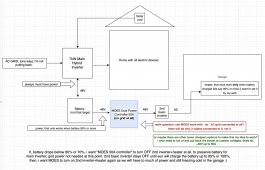
I made this schematics, please take a look:
Maybe i need simple relay? :D but 48V 50A is not simple i believe
i just looked once again carefully and you are right. It passes only AC ±220V on all 3 rails, only the 4th port is for DC. I haven't bought it yet, i'm just looking for a solution right now. Found this device, it looked very well, with a lot of good reviews, i just somehow did not locked carefully. In the beginning i'm interested on two different solutions, that maybe can have two different ways to solve it. I would like to have one relay for device that is 1500W of load, so 48V and 40/50A (with some extra on the top), as well it would be interesting to have similar but smaller 48V 15A-20A. also fully adjustable. If you have something to recommend, for such a switching i would be very thank full.Here is my understanding of what the objective is:well, you've pointed in to very correct place, that i've missed out
You could go ahead and wire in your second inverter and then put the output of the inverter into the inverter input on the ATS and it then monitors the battery voltage and you can then set the microcontroller to engage and pass the inverter output to your garage when the battery voltage is where you want it to be. The downside to that is even when the ATS doesn't switch in the inverter output it will still be sitting there eating up battery power...although most inverters use minimum power when not engaged.well, you've pointed in to very correct place, that i've missed out
Here is my understanding of what the objective is:
*When the battery is full or near full, let the heater in the garage turn on. This allows the energy that would otherwise be wasted to be used.
Question: Is there a reason for the 2nd inverter? If you could accomplish the objective without the 2nd inverter would it be acceptable?
The reason I ask is that if you had a signal to drive a relay when the batteries are full, you could throw a relay to turn on the heater that is powered by the main AC. Many devices have a programable relay that could accomplish this goal.