diy solar

diy solar

New no battery pure sine wave solar power system with smart switchers.

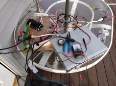
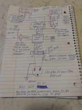
Will prepare tonight for the ISO test tomorrow weather permitting, will be a small amount of work to keep it separate from the working house systems, tomorrow we are going to dig to the absolute bottom of a rabbit hole and see what is waiting.
See you soon.?

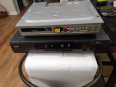
Will be using (borrowing) the fridge switcher to test interactions with grid during the test, should not matter but must test 120 Volts from each side of the power panel and test all four possible power configurations.
Wether permitting it's going to be exciting tomorrow.?

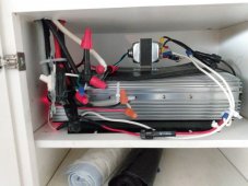
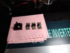
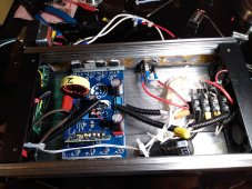
Ready for testing tomorrow, I have one good reason why it may run smooth and one strong reason why this may end in a quick fail, everything will be glass fused at normal operation amps, past experiences with bias faults burn up the center of the power board and explodes the cap making for a burned mess.
I would take bets but need it to work to save money and to get the highest efficiency possible.?

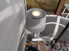
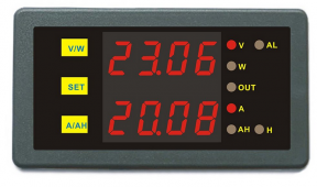
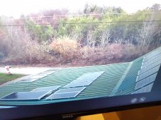
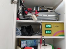
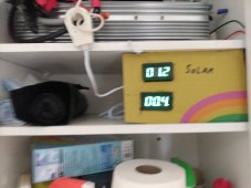
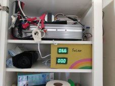
By the way beautiful solar day and new 2000 watt power system is performing perfect.
 
Last edited:
Good morning everyone, just completed the ISO testing on the pure sine power board.

Home Run ! After numerous tests (direct drive opposite phased 120 volt AC in 4 different configurations)
(Seamless transfer between solar and grid, transfer grid to grid, solar to solar)

Don't know if it is the diode bridge or blocking diodes but the power board does not care on the input side where the energy comes from ?

New rules based on this mornings test, only one Isolation transformer is needed on the power board output 120 VAC 15-16 amps and if you power the CPU and fans from a grounded power system you need a 16volt door bell transformer to isolate that power board system.
Last power system diagram is correct except CPU must be powered 24/7 for seamless transfer options.
Both solar and grid/alternate 120VAC will directly drive the power board and work efficiently.?

5 years old power board lives to see another day, this seriously changes everything for the better.

As of this morning I have witnessed several seamless transfer operations, one of the big hurdles of this project, just a dream when I built the first switcher.✅

(Warning later testing proved several statements made above to be wrong, simply put all grounded or negative ground power connections require a Isolation transformer!)
 

Attachments

  • IMG_20221110_090707328.jpg
    IMG_20221110_090707328.jpg
    304.6 KB · Views: 10
  • IMG_20221110_090702774.jpg
    IMG_20221110_090702774.jpg
    280.3 KB · Views: 10
Last edited:
I wired the fans for continuous operation from the 16 volt door bell transformer with a diode bridge and a dropping resistor to make them run at 1/3 speed, did that so the Blocking diodes and Diode bridge get a constant flow of cooling, If you use the fan output on the power board make sure the little black temp sensor touches the case, make sure your fans are operational.

Need to reconfigure the 2000 watt system for seamless operation, ISO transformer in the mail will be the heart of new 800 watt direct drive system, Scored the 1000 watt ISO new on Amazon for under $200.
 
✅ Direct drive high efficiency solar.
✅ Direct drive secondary power.
✅ Seamless transfer of power.
✅ Impossible to back feed the grid.
✅ Have actually tested 1700 watts of pure sine power from the new expandable system.
✅ Runs everything but need a 2500/3000 watt capacity board and panels configuration to do car charging.

Have four 1000 watt boards available if I can sync 3 of them for 3000 watt capacity ✅ on EV car charging.

I am not interested in battery storage on this system but it could easily be added, this thing charges the heck out of LI-ION batteries.✅

In all my years as an industrial tech and seven years working with solar
Have not seen anything close to this in compact size and efficient operation, please take a look.?

Could easily fit two of these in one standard inverter case, from this mornings testing two of the blocking diodes off the diode bridge are not needed.?

New updated diagram of the system. Nov 14 new safety fuse.
 

Attachments

  • IMG_20221114_161320585.jpg
    IMG_20221114_161320585.jpg
    138.5 KB · Views: 6
Last edited:
Just occured to me, I did every conceivable test I could think of this morning and they all passed.

But I have lost 4 of the 1000 watt boards due to bias damage in three separate incedences each time I recognize it was bias damage because the units exploded the second I connected the CPU power to another grounded power system, each time in response I broke out the door bell transformer and ISO transformer and the problem vanished.

Here comes the kicker what if the door bell transformer is all that is needed to protect the power board?
(This statement was proven wrong in later testing, ISO transformers are needed to protect from grounded and negative ground bias power connections)

Don't really want to kill the 5 years old power board but I need to know for sure if the main Isolation transformer is actually needed, supposed to rain tomorrow but first chance I get we are going to retest and find out for sure.?

Wish I had thought of this earlier, but yet again today was a great day no boom.

Easy to test just run the power board output directly through a grid powered and grounded switcher unit and we will know for sure.

More thinking the Isolation transformer does more than just protecting the power board it also corrects the power for proper neutral and ground, Ok I am done except for automation?
Right now thinking about a multiple level sun sensor, different modes to best handle (Off not enough sun),(seriously overcast - Low),(medium sky),(Full sun)
Command the power unit and switchers for maximum benefit.
Think about a unit with four seamless power boards.? I can do that have four 1000 watt power boards two new in the plastic bags.

Not a new concept my Gopower unit does a Simi good power blending that is currently the way car charging is handled, but this dual seamless input could be expanded to quad and more with multiple power boards, put on a micro controller to do real magic.
 
Last edited:
Good morning 3:40 AM

New idea ?
No sun sensor needed, just plug the unit in and monitor grid/secondary power usage, the slightly higher voltage solar panels will block grid usage during the day and if a cloud passes or sun sets the unit will pull what it needs seamlessly from the secondary power source.

This is exactly what I am going to start testing as of today and I will report back how it works ?

Once again I think I have come up with the ultimate in seamless solar power.?

After the storm clears out going to add another string of 9 solar panels for 1700 watts.
 
Last edited:
It is done ✅ no sun sensor.

Secondary input is fused at 10 amps. And permanently monitored by a really nice current sensor coil and "O" scope ?

CPU and fans powered 24/7 from the older Gopower system.

House lights are on the 2000 watt power unit and awaiting sun rise.?

Deluxe switcher is no longer connected to the system.?

Nine panels on the roof, ISO transformer is in the floor the rest of the system fits comfortably on one shelf, just keeps getting more compact and functional.

Needs indicator lights to show system status, already have CPU status LED on the inside and red neon high voltage indicator, add two digital amp meters for solar input and the secondary input so one look will tell you everything.?
 

Attachments

  • IMG_20221111_060438519.jpg
    IMG_20221111_060438519.jpg
    205.5 KB · Views: 4
Last edited:
Confirmed only one ISO transformer and one 16 VAC door bell transformer needed to run safely.

(Later testing proved this statement false, ISO transformer is needed for any grounded or negative ground power input)

If not for the successfull testing yesterday no way I would have connected my system in this manner today, so far working stable.?

Ordered 2 hall effect digital DC amp meters also plan three power indicators and a CPU status indicator, It's going to look cool.?

Glass fuses as follow:
Two 1amp for each side CPU power.
Two 10 amp on secondary 120 VAC input, can run 15 amp for 2500 watt system if diode bridge is also rated 15 amp.
One 2 amp fuse on 120 volt input to door bell transformer 16 VAC out.
One 5 amp glass fuses for each set of nine standard 100 watt PV panels 180 VDC!
See detailed drawing for other fuse sizes.
Proper wire type,size, fusing and switches are important on this project.
 
Last edited:
Getting close to the end of the solar day and would like to start telling you the good news.
Today was a typical rainy day with one blast of 15 minute full sun around 3PM.
Collected lots of data on the system operation, the unit is a high efficiency power blender, It works amazingly well because the PV voltage is higher than secondary input, takes advantage of all available solar and stops the flow of secondary power.
Experienced no faults or flicker in the lights or fans today.
Bottom line it works, beyond expectations it works, quantum leap forward it works.?

Security cams are now on night vision, as a end of day test I turned on all lights and fans about a 550 watt load and checked again, everything is running cool and efficient on secondary power.✅

ISO testing was the key to the big step forward, second ISO transformer 1000 watt arrived a few hours ago, tested good will be perfect for a 800 watt seamless starter system.

( This isolation transformer ended up fixing the remaining issues with the main system and allowed for a big win for the project ?)
 
Last edited:
Have ordered two digital DC amp displays, CPU status, CPU power, Hi voltage detector and secondary power indicator lights.
Here is a sample display similar to what I have in mind.?
Coming soon to this project.
 

Attachments

  • Screenshot_20221111-210529~2.png
    Screenshot_20221111-210529~2.png
    230.6 KB · Views: 3
Safety first never put yourself in a position to get shocked, wear rubber gloves, after any hot test pass or fail you can discharge any large capacitors with a 40 watt standard light bulb first and a final check with a plastic handle screw driver last, most of these power boards can be discharged from the main DC input wires. Never assume anything with DC that 10 years old capacitor can still be a problem.

Most solar enthusiast already own the components needed to build one of these super seamless high efficiency power systems, any pure sine inverter with separate power output board (pure sine required to work with the ISO transformer correctly) or old standard power inverter case that can accept a replacement pure sine power board will do, dump the two third sized boost section and cut the wires long to your advantage from the power board, install the dual input blocking diodes module and Diode bridge into the case, follow the diagram closely (ask questions or get help if in doubt about anything)
Any matching set of panels that produce 180 VDC! +-5% will work for this project, mix panels may work fine but have not been tested.
After just one full day with the new power system trust me on this you really want one!, especially if you can take stuff you already own reconfigure and presto.?

Just to be clear you do not need the sun sensor control or switcher units, the most automatic seamless power transitions ever just invented in the past 3 days.?

This huge leap forward is the direct results of Isolation testing 3 days ago on the replacement power board and a trick of nature that says the highest voltage wins in a power blend situation.

Just read the post again, I am not suggesting that you use a pure sine inverter that you are already using for power production but a spare or like my Vertamax inverter the whole lower half boost section fried but the output power boards were still good, all you need to start and build up the project system.
Standard power requirements for power board controller CPU is 12-18 VDC if the wires go to four diodes 16 VAC is normal, If you power this from a negative ground or grounded power system you will need a doorbell or ISO transformer to not damage the power board.

New Nov14 updated, one additional glass fuse 10 amp on secondary 120VAC.
 

Attachments

  • IMG_20221114_161320585.jpg
    IMG_20221114_161320585.jpg
    138.5 KB · Views: 7
Last edited:
I have a good suggestion if you are interested in such things, watch a couple hours of YouTube videos on inverter repair and FET replacement.

Installing a new power board in an old inverter case is not so hard once you have seen it done.?

You watched me totally build from kit and rebuild a 2000 watt pure sine power board, you can repair the output power board of any old pure sine inverter and lay the ground work for the new seamless power system, normal for just the FETs to fail, on my crown jewel 2000 watt board 4 of 8 FETs were bad, replaced all 8 FETs with new also had to replace the small CPU board to restore operation, won't make the same mistake ever again.?
 
Last edited:
Coming to a close on the second solar day with the seamless power system, Just hard to express how happy I am the direction the project is going, never imagined totally getting rid of the power switchers.

Next push is to fully automate the system, their is a commercially available App Controlled Outlet 120 VAC that response to voice commands and remote phone app control, for easy explanation I will call it a "ACO"

ACO on door bell transformer for main unit control on/off function.
Let's say six ACOs on the 120 VAC output to control all your stuff.
Setting the ACO time of day on and off time you can select what will run on solar and what consumes after hours secondary 120VAC power.

Things get busy around the holidays likely January before I get all the bells and whistles working ?
 
Last edited:
My main Gopower unit never made it out of the hole today because of cloudy weather, testing on the new system suggest every solar panel I own should be on the new concept power systems.

I am going to keep the older system working enough to keep the batteries hot and use it like a UPS for critical systems and power all the new CPUs on the new seamless power board systems.?

Deluxe switcher and mini split switcher just lost their jobs.

I found out three power boards will fit in a standard inverter case, when I get the time going to put three synced power boards in one case for EV car charging.

Ordering three App Controlled Outlets. Main unit control, Day stuff, night stuff and directly connected stuff.?
Toggling the main power does a hard reset of the power board CPU.

Currently building a second dual input power module with blocking diodes and 120 VAC diode bridge, Will be installed in the 1000 watt unit that was removed from service coupled with the new ISO transformer to make another seamless power system.
 

Attachments

  • IMG_20221113_181545992.jpg
    IMG_20221113_181545992.jpg
    196.1 KB · Views: 7
Last edited:
Ready to upgrade 1000 watt unit, diodes came from one of the dumped boost sections, lots more where those came from,diode bridge is rated for 40 amps over kill for what we need 10-15 amps but I will sleep better knowing it can handle the needed task.
 

Attachments

  • IMG_20221113_202151566.jpg
    IMG_20221113_202151566.jpg
    163.6 KB · Views: 8
In the final stages to permanently upgrade the new system to 1700 watts on the 2000 watt capable board, final changes will take place after sun set for safety.

After another circuit audit, redraw of the power system with one additional safety fuse on the secondary 120VAC.

Attached photo disregard all previous drawings.?

If the CPU or fans need DC power to operate use a diode bridge and filter capacitor on the output of the door bell transformer to supply needed power, 24/7 power to have seamless power transitions.?
 

Attachments

  • IMG_20221114_161320585.jpg
    IMG_20221114_161320585.jpg
    138.5 KB · Views: 4
Last edited:
Have corrected miss dated drawing, sorry real people here.

In case you are interested the PV panels that are part of the new 180 VDC chain are the largest panel in the view the relocated panel just beyond it, the four on the left side and the last two on the top row, meter readings look good ?
 

Attachments

  • IMG_20221114_163244547.jpg
    IMG_20221114_163244547.jpg
    255.1 KB · Views: 7
Unit back in place and ready for sun up two strings of panels 1700 max watts on a 2000 watt power board.
During high load testing found a crimp connector on a blocking diode that had a bad connection (Caused a buzzing noise), cut out all the crimp connectors and soldered in the connections ?
Bench testing has proven the unit is ready for prime time, hope I get 10 years out of it.?

The white blob you see in the spot light is the sensor coil for the new digital amp meters I ordered.?

For me ten turns through the 100 amp coil should give a nice range but unfortunately I only had enough wire for two loops, have to go back in later for indicator lights anyway at that time will fix the loops to ten.

Good night all?
 

Attachments

  • IMG_20221114_210639119.jpg
    IMG_20221114_210639119.jpg
    294.4 KB · Views: 7
Last edited:
Good morning 6AM

Before sun up and pouring rain outside. I will add interesting photos to this post as things progress.
Each amp meter is 100 amp max to get things started two turns through each sensor coil, solar on top alternate 120 VAC on the bottom.

Let the fun begin.?

Each coil needs 10 turns each, to display the expected 0-10 amps in high detail, The numbers will be low during this initial test but we all will get to see exactly how it works.

Going to add several indicator lights later at that time I will go 10 turns each on each of the sensor coils.?

The decimal in the lower right corner indicates reverse DC flow,I did not set these up any particular way but OK with alternate power showing up as a negative number.

Tomorrow will be a much better day, hope it clears some in the late afternoon today. Still raining heavily solar starting to win,last pic 2:20 PM Nov 16 sun finally shining.

After sunset today I will reverse the loop/current direction on the solar amp meter.?
 

Attachments

  • IMG_20221115_061247121.jpg
    IMG_20221115_061247121.jpg
    215.2 KB · Views: 9
  • IMG_20221116_114104751.jpg
    IMG_20221116_114104751.jpg
    172 KB · Views: 8
  • IMG_20221116_141818076.jpg
    IMG_20221116_141818076.jpg
    193 KB · Views: 8
Last edited:
Total bad solar day never stopped raining, new concept system can do well on a gray day but can't get much traction once rain has started.
Even with the heavy rain the system generally provided two third solar to one third secondary power all solar day.

1000 watt power board has been upgraded to seamless power operation and awaiting final bench testing, coupled with the new ISO transformer another 800 watt system lives.

Just passed final test with ISO transformer built dual power input header on top of the diode bridge used crimp connector spades (removed plastic sleeve) and soldered in the diodes after crimping, turned out nice and servived load testing.?
 
Last edited:
Back
Top