diy solar

diy solar

New SOK Bluetooth BMS for DIY

@FilterGuy Thanks for the update I just switched took my BT BMSs out and put the non-BT ones I originally had back in. I only have two 206Ah batteries and the new BT BMS could only deliver 230A total. I need more like 300A for my MultiPlus II 12/3000.
 
To turn the D-Mos back on, you must put a sufficient charge voltage on the battery. The charge voltage must be a little bit higher than the internal battery voltage. (This confused me for a while when I had the charge voltage turned down a bit and it was not restarting the battery)
If you are shut down on SCP, you can hit the current calibration button, type in 200010 for the calibration password and then type in 0A (the battery wouldn't have any current going in/out anyway if it's in SCP) and then hit cancel when you reach the dynamic current calibration. This process will reset the protection.

We've got a long list of things going in our engineering chat for how to make these batteries better and make the app more intuitive. There are a lot of changes coming. For example the process of charging to full and then completely draining to make SOC% accurate is silly.
 
Just did a build with 2 SOK 12V 100Ah, Heated w/ Bluetooth batteries and a Victron 2K Multiplus, a Victron Orion TR Smart, and a Victron SmartSolar 100|30
And another thing I learned:

8) One of the batteries reported something like 400 Cycles in the app when it was first booted up. SOK assured us in an email that it is a brand new battery and the high cycle count is a bug that they are working on. (It is not clear to me if it is an app bug or BMS firmware bug.....my guess would be that it is a Firmware bug)
 
If you are shut down on SCP, you can hit the current calibration button, type in 200010 for the calibration password and then type in 0A (the battery wouldn't have any current going in/out anyway if it's in SCP) and then hit cancel when you reach the dynamic current calibration. This process will reset the protection.

We've got a long list of things going in our engineering chat for how to make these batteries better and make the app more intuitive. There are a lot of changes coming. For example the process of charging to full and then completely draining to make SOC% accurate is silly.
Thank you for the update. It is good improvements are being made.

A few things that would be high on my list are:
1) When the D-MOS or C-MOS is off, an indication of *why* they are off.
2) An ability to at least see the balance settings and balance activity. Ideally, I would be able to change the balance settings.
BTW: What is the balance current? Is it Passive or Active?
3) Thankyou for the 'turn on' trick, but it would be nice to have something a bit more specific for turning it on (and off)
4) I have not measured it, but rumors are the BMS has a high current load all the time. There should be an idle mode that is very low current when nothing is going on. Maybe even go as far as turning off Bluetooth.... but wake it up every once in a while to see if anything wants to connect.
5) A way to put the battery into a storage mode that uses as little power as possible. Perhaps this would even shut down Bluetooth and require a charge voltage to restart.

Note: If any of the above require a FW update, there needs to be an easy and relatively safe way to update the firmware.
 
Last edited:
If you are shut down on SCP, you can hit the current calibration button, type in 200010 for the calibration password and then type in 0A (the battery wouldn't have any current going in/out anyway if it's in SCP) and then hit cancel when you reach the dynamic current calibration. This process will reset the protection.

We've got a long list of things going in our engineering chat for how to make these batteries better and make the app more intuitive. There are a lot of changes coming. For example the process of charging to full and then completely draining to make SOC% accurate is silly.

will this work to reset the D-MOS protection as well? If so, that is very helpful. I just don't see any reason not to let people take it out of D-MOS protection on on their own.
 
will this work to reset the D-MOS protection as well? If so, that is very helpful. I just don't see any reason not to let people take it out of D-MOS protection on on their own.
The SCP (Short-Circuit Protection) will turn off the D-Mos (Discharge Mosfets). I have not tried it yet, but presumably, the trick described will turn the D-Mos back on after an SCP event.

There are other events that can turn off the D-mos
  • Over Current
  • Over temp
  • Under temp
  • Under Cell Voltage
  • Under Battery Voltage
I suspect the trick will work for any of the events that are not still occurring. Examples: 1) If it is still under-temp, the trick probably won't work. 2) If a Cell is still under voltage the trick probably won't work)

This leads to one of the things that are on the wish-list I gave him above: An indication of what caused the D/C-Mos to turn off.
The problem is that I so far have known the cause 100% of the time. In my case its always an under voltage or over current. When experimenting in my camper with what can/cant be run by the inverter, it would be helpful to just be able to flip the damned thing back on when it goes into protect.

Example, I can use my chop saw off the inverter, but every 100 cuts or so it puts the battery into protect. Then comes 15 min of screwing around with a charger when all I need is to reset the damned thing.
 
Thank you for the update. It is good improvements are being made.

A few things that would be high on my list are:
1) When the D-MOS or C-MOS is off, an indication of *why* they are off.
2) An ability to at least see the balance settings and balance activity. Ideally, I would be able to change the balance settings.
BTW: What is the balance current? Is it Passive or Active?
3) Thankyou for the 'turn on' trick, but it would be nice to have something a bit more specific for turning it on (and off)
4) I have not measured it, but rumors are the BMS has a high current load all the time. There should be an idle mode that is very low current when nothing is going on. Maybe even go as far as turning off Bluetooth.... but wake it up every once in a while to see if anything wants to connect.
5) A way to put the battery into a storage mode that uses as little power as possible. Perhaps this would even shut down Bluetooth and require a charge voltage to restart.

Note: If any of the above require a FW update, there needs to be an easy and relatively safe way to update the firmware.


1.) The newer version BMS shows this information in the Protection State screen. Unfortunately, older BMS's won't be able to see this information because the MCU doesn't report it to the app.

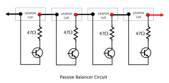
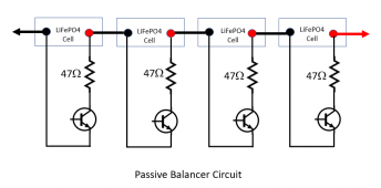
2.) How would you like to change these settings? Like, the voltage when the balance function starts and ends? The balance function is passive and the current will change a bit based on the BMS version as it's limited by the balancing shunting resistors that are on the PCB. The original BT BMS uses 47Ω resistors for this, but the duty cycle for the balancing is not 100%.. max 70% it seems.

3.) Agreed. Asking for that.

4.) The original BT model has an average of about 10mA draw. I haven't measured newer version BMS's yet, but I'm told newer versions will have even less. We also worked with the VMS developer to implement an under voltage lockout circuit as severe undervoltage was causing the MCU to corrupt flash memory (and is a potential cause for the high cycle count as well)

5.) Agreed. That would be ideal! Brought this up before but will bring it up again.
 
The problem is that I so far have known the cause 100% of the time. In my case its always an under voltage or over current. When experimenting in my camper with what can/cant be run by the inverter, it would be helpful to just be able to flip the damned thing back on when it goes into protect.

Example, I can use my chop saw off the inverter, but every 100 cuts or so it puts the battery into protect. Then comes 15 min of screwing around with a charger when all I need is to reset the damned thing.
The trick Dexter mentioned will work in that situation. I agree that a switch or a simple click in the app would be nice. We are working on getting them to implement this.
 
1) When the D-MOS or C-MOS is off, an indication of *why* they are off.
1.) The newer version BMS shows this information in the Protection State screen. Unfortunately, older BMS's won't be able to see this information because the MCU doesn't report it to the app.

The batteries were just purchased a month or so ago..... how new do they have to be? Is there any way to get a version number or something that lets me know what I have? BTW: For something like SCP, the indication needs to persist till the battery is turned back on.... not just indicate a short for the few milliseconds before the battery shuts down.

Can the firmware be updated to add this feature?

2) An ability to at least see the balance settings and balance activity. Ideally, I would be able to change the balance settings.
How would you like to change these settings? Like, the voltage when the balance function starts and ends?
Exactly.

3) Thankyou for the 'turn on' trick, but it would be nice to have something a bit more specific for turning it on (and off)
3.) Agreed. Asking for that.
Thank You

4) I have not measured it, but rumors are the BMS has a high current load all the time. There should be an idle mode that is very low current when nothing is going on. Maybe even go as far as turning off Bluetooth.... but wake it up every once in a while to see if anything wants to connect.
4.) The original BT model has an average of about 10mA draw. I haven't measured newer version BMS's yet, but I'm told newer versions will have even less. We also worked with the VMS developer to implement an under voltage lockout circuit as severe undervoltage was causing the MCU to corrupt flash memory (and is a potential cause for the high cycle count as well)
Again..... What does "newer version BMS" mean? These batteries are brand new. How do I tell what version I have and what is the new version?

BTW: I have the High cycle count issue. Does that mean I have a corrupt flash? Is there a way to reset it? This news is kinda disturbing because SOK also instructs us to run the battery all the way down twice to train the SOC. Is this action creating a risk of corrupting flash?

BTW: The only reason I did not add a better way to train the SOC was that @HighTechLab said it was being worked on.

5) A way to put the battery into a storage mode that uses as little power as possible. Perhaps this would even shut down Bluetooth and require a charge voltage to restart.
5.) Agreed. That would be ideal! Brought this up before but will bring it up again.
Thank you for pushing. These 100Ah Batteries were chosen because they are physically sized to replace the RV Lead Acid batteries quite nicely. Very little had to be done to make them fit. A lot of RVs are stored more than they are used so a storage mode would be an ideal match for the use case.
 
Last edited:
The batteries were just purchased a month or so ago..... how new do they have to be? Is there any way to get a version number or something that lets me know what I have? BTW: For something like SCP, the indication needs to persist till the battery is turned back on.... not just indicate a short while it is happening.

Can the firmware be updated to add this feature?


Exactly.


Thank You


Again..... What does "newer version BMS" mean? These batteries are brand new. How do I tell what version I have and what is the new version?

BTW: I have the High cycle count issue. Does that mean I have a corrupt flash? Is there a way to reset it? This news is kinda disturbing because SOK also instructs us to run the battery all the way down twice to train the SOC. Is this action creating a risk of corrupting flash?

BTW: The only reason I did not add a better way to train the SOC was that @HighTechLab said it was being worked on.


Thank you for pushing. These 100Ah Batteries were chosen because they are physically sized to replace the RV Lead Acid batteries quite nicely. Very little had to be done to make them fit. A lot of RVs are stored more than they are used so a storage mode would be an ideal match for the use case.
You can determine the BMS version by looking at the Date of Manufacture in the Detail screen on the app. The original V1 BT BMS will be in October 2021. I am not sure which version started showing Protection State, but I know it shows at least starting in April 2022 Date of Manufacture. The Protection State indication will persist until the state is cleared.

Theoretically, the firmware can be updated to have the BMS show the protection state in the app, but that requires a special programmer and a firmware that works on the original BMS hardware that implements the protection state information transfer. As far as I know, no one in North America or Europe has this programmer or software (yet?).

No, you don't have corrupt flash. If you did, the battery would be unusable. I was not clear on the original post, but the high cycle count and corrupt flash are different faults caused by the same condition. For the flash corruption, I am not 100% sure but my theory is that the MCU voltage is too low to interpret the instructions in the flash properly and it starts misreading instructions, then potentially overwriting important flash data. For the cycle count, it could be the same idea, but I think what's probably happening is the chip that reads the cell voltage and reports it to the MCU is in a gray area regarding operating voltage range and can't accurately measure the cell voltage.. it then reports erratic cell voltage to the MCU and the MCU thinks the cells are being cycled. I have never witnessed this happening, so it's just a guess at this point.

Running the battery down normally will not get the cells anywhere NEAR this low voltage range.. we're talking sub 5V, sub 3V that causes this issue. Since the BMS has a tiny current draw, this will only happen if the battery is left to sit for a LONG time.

FYI since the draw is roughly 10mA, that translates to about 10% every 40 ish days on a 100Ah. If you charge to 100% before storage, they can sit for over a year without issue.
 
The balance function is passive and the current will change a bit based on the BMS version as it's limited by the balancing shunting resistors that are on the PCB. The original BT BMS uses 47Ω resistors for this, but the duty cycle for the balancing is not 100%.. max 70% it seems.
I have a run-away cell in each of my two batteries, so I am interested in how quickly the balance circuit can correct things.

Edit: Clarified description
You are saying there is a 47ohm resister between the cell positive and negative. If the cell is at 3.5V and the controlling transistor has a .6V drop the balance current will be (3.5V-.6V)/47R=0.0617A

Edit: Added schematic for clarity.
1661366103389.png

On the 100Ah cell, if it is 2Ah higher charged than the others, it will take over 2Ah/.0617A = 32.4h to balance.

I do not have detail on when the balancer is on or off, but if it is like most balancers, it is only on at the very end of the charge cycle (as it should be). If we assume it is on for 1/2 hour each charge cycle, it will take over 65 cycles to balance.

Are my assumptions correct? Am I in the right ballpark?
 

Attachments

  • 1661366153021.png
    1661366153021.png
    41.9 KB · Views: 0
Last edited:
Edit: Clarified description
You are saying there is a 47ohm resister between the cell positive and negative. If the cell is at 3.5V and the controlling transistor has a .6V drop the balance current will be (3.5V-.6V)/47R=0.0617A

Edit: Added schematic for clarity.
View attachment 108308
This is mostly correct. In the case of BJTs, there won't be a 0.6V drop since the controlling IC (in this case, TI's BQ76920) can drive the transistor's base high enough to get the transistor into saturation, so you'd only have a small Vce drop. However, I am fairly certain the BMS uses MOSFETs in place of BJTs.. it was a while ago that I measured, but I'm fairly certain I measured a diode where the body diode of a MOSFET would be expected to be, and not two diodes between CB and BE like a BJT would measure. I'll confirm when I have a BMS and a multimeter to verify. Assuming it IS a MOSFET, you'd only have Rds to consider. I don't have the transistor information as the conformal coating on the BMS makes it very difficult to distinguish the markings, so I don't have any spec sheet to go on, but the Rds should be small compared to the 47Ω balance resistor so it's negligible. In this case then the balance current at 3.5V would be 3.5V/47Ω=74mA
On the 100Ah cell, if it is 2Ah higher charged than the others, it will take over 2Ah/.0617A = 32.4h to balance.
The maximum duty cycle for the balance function is max 70%. This is because the TI's ADC needs some time to read the voltage first (a more detailed explanation can be found in the BQ76920's datasheet if you're interested). As such, the absolute maximum balance current would be:

2Ah/(0.074A*0.7) = 38.6h

I do not have detail on when the balancer is on or off, but if it is like most balancers, it is only on at the very end of the charge cycle (as it should be). If we assume it is on for 1/2 hour each charge cycle, it will take over 65 cycles to balance.

The balance function, from what I understand, is not time based, but voltage based. I am told by SOK that the balance function will be active as long as ANY cell is above 3.4V. I have not verified this personally so I cannot say if this is 100% accurate or not. The old, non Bluetooth BMS used a different IC and its balance function was active with any cell above 3.5V (I did personally verify this). One thing to note about the Bluetooth BMS compared to the non Bluetooth is that the CMOS will automatically re-engage as soon as all cell voltages are below 3.65V. This means that if you keep a charger on it that tries to keep the voltage at say 14.4 or more volts using something like a bench top power supply, the balance function should always be active. The old BMS kept the CMOS FETs off until it measured a discharge.

Are my assumptions correct? Am I in the right ballpark?

Right ballpark you were indeed (y)

If you're interested, I made a schematic for the balance circuit a while back. This isn't from SOK, but the component designations and values are in line with the version 1 BT BMS.

2022-08-25 13_56_37-Eeschema — SOKBMS2022v6.sch [_] — C__Users_Dan_Documents_SOK_2022BMS_SOKBM...png

This repeats for each cell.
 
@kinyoubi Thank you very much for the detailed response!! It is very helpful!

I am told by SOK that the balance function will be active as long as ANY cell is above 3.4V.
Does this mean the balance function will remain on while a cell is above 3.4V even if the chargers turn off?
One thing to note about the Bluetooth BMS compared to the non Bluetooth is that the CMOS will automatically re-engage as soon as all cell voltages are below 3.65V. This means that if you keep a charger on it that tries to keep the voltage at say 14.4 or more volts using something like a bench top power supply, the balance function should always be active.
Yes. I observed that the charge MOS Fets automatically turn back on when the voltage drops. I generally set chargers to 14.2V (not 14.4V) but from what you describe, it should still balance the cells.

The balance function, from what I understand, is not time based, but voltage based.
Yes, understood. I was overlaying a time by guessing how long the conditions would be true for balancing during a charge cycle. If the balancer stays on even after the charge stops, it will certainly change the equation, but it is hard to predict by how much.
 
Does this mean the balance function will remain on while a cell is above 3.4V even if the chargers turn off?

Yes, this is my understanding.

One more question: At what cell differential voltage level will the balance system turn off?

I actually am not sure about this! It seems this is determined by the microcontroller, so I'll ask for this information and report back.
 
Thanks for the update.

Sure thing! Thanks for the question.

For whatever it is worth, 25mV will work but I prefer a lower balance goal.

This may be something I can push for being a value that can be modified via the app if it's not hardware limited. If 25mV is software controlled then I think being able to set it within a range might be nice..
 
@FilterGuy
The balance function, from what I understand, is not time based, but voltage based. I am told by SOK that the balance function will be active as long as ANY cell is above 3.4V. I have not verified this personally so I cannot say if this is 100% accurate or not.

Does this mean the balance function will remain on while a cell is above 3.4V even if the chargers turn off?

So I originally said yes, from my understanding, since this is what I was told.

I have been looking into the MCU's flash and found today that my understanding was slightly incorrect..

The balance function will only turn on if the charge current is more than 1 amp. The 3.4V cutoff and 25mV difference is correct. As far as duty cycle goes, the MCU enables the balance cycle for 0.6 seconds, then keeps it off for the rest of the second.. in other words, a max of 60% duty cycle. The BQ76920 still has its own duty cycle limitation (70%), but the MCU's is lower for some reason.
 
Back
Top