diy solar

diy solar

Question re: joining 10 AWG panel wire to higher gauge for long run

jsocolof

New Member
Joined
Jan 20, 2022
Messages
45
Hi from Colorado. I am new to the forum, and found it because I am in the initial stages of planning an off-grid PV setup for a mountain cabin. Initial system is planned to be 6KW of panels, a Sol-Ark SA-12K inverter, and several EG4 batteries. I'm sure I will have many questions for the group, but the current one involves transmitting the DC from the panels to the inverter, which will be over a distance of about 200 ft. I plan to have 8 panels in series in each of two parallel strings (perhaps REC REC370TP2SM72 375W, 40.1V, 9.4A). Total amperage 18.8, total voltage 320.8. System voltage is 48VDC. Wiring at the panels is of course 10 AWG, and the Sol-Ark takes 10 AWG on the PV inputs. Transmitting over the 200 ft distance requires #2 wire to minimize voltage drop. I would like to put a panel disconnect out by the panels, and another inside by the inverter so I can disconnect at either end for service. I was hoping to find a fusible disconnect that would allow 10 AWG and #2 connectors on opposite lugs so I could connect the panels on one side of the disconnect and the wire for the long run on the other side. Failing that, I could use a 10 AWG disconnect at the panels and then buy/make some sort of lugged outdoor box to connect the 10 AWG to the #2 wire.

So, the questions are: Is what I'm describing a sound plan? If so, is there a recommended disconnect? Does the collective wisdom on this forum have a better approach to what I am describing?

Thanks in advance.
 
Given the voltage you will only lose about 3% using 10AWG across the whole 200'. I see no reason to use 2AWG. If it was 12V then yes. But not at 320V.
 
Total amperage 18.8, total voltage 320.8. System voltage is 48VDC. Wiring at the panels is of course 10 AWG, and the Sol-Ark takes 10 AWG on the PV inputs. Transmitting over the 200 ft distance requires #2 wire to minimize voltage drop.
Need to look at this closer. 3% of 320.8V is 9.62V. If the current ever gets to 18.8A (and it probably won't since that is the nameplate rating, which is greater than reality), then the resistance on the wire to 3% drop is 9.62V / 18.8A = 0.512 ohms. If distance is 400 ft, the resistance per foot is 0.512 / 400 = 0.00128 ohms / ft,, or 1.28 ohms per 1000 ft. NEC table indicates that 10 AWG wire has a resistance less than 1.2 ohms per thousand foot. So if you go by the normal goal of < 3% drop in the wire, 10 AWG the whole way is plenty big enough.
 
Suggest non-fusible disconnect.
Square-D "heavy duty" 600V AC/DC 30A 3-pole switch. Available rain tight NEMA 3-R, also indoor NEMA 1.
I think another brand (Siemens?) has a 250V rated one. 2 poles in series could do it.

You can also get DIN-rail DC breakers from Midnight or Schneider. Two or more poles in series, adding up to sufficient voltage rating.
 
What calculator did you use to come up with 2AWG wire? It comes out to be 10AWG for 3% Vdrops.
 
Last edited:
Which one? Every calculator I've tried shows about a 3% drop for 18A at 320V over 200' (one way) with 10AWG
I think I entered it at 400' for the round trip and that was incorrect. 10 is fine or overkill it with 8.
 
I think I entered it at 400' for the round trip and that was incorrect. 10 is fine or overkill it with 8.
It is 400' round-trip. But many calculators have you enter one-way. And your original reply stated 6AWG, not 8AWG.
 
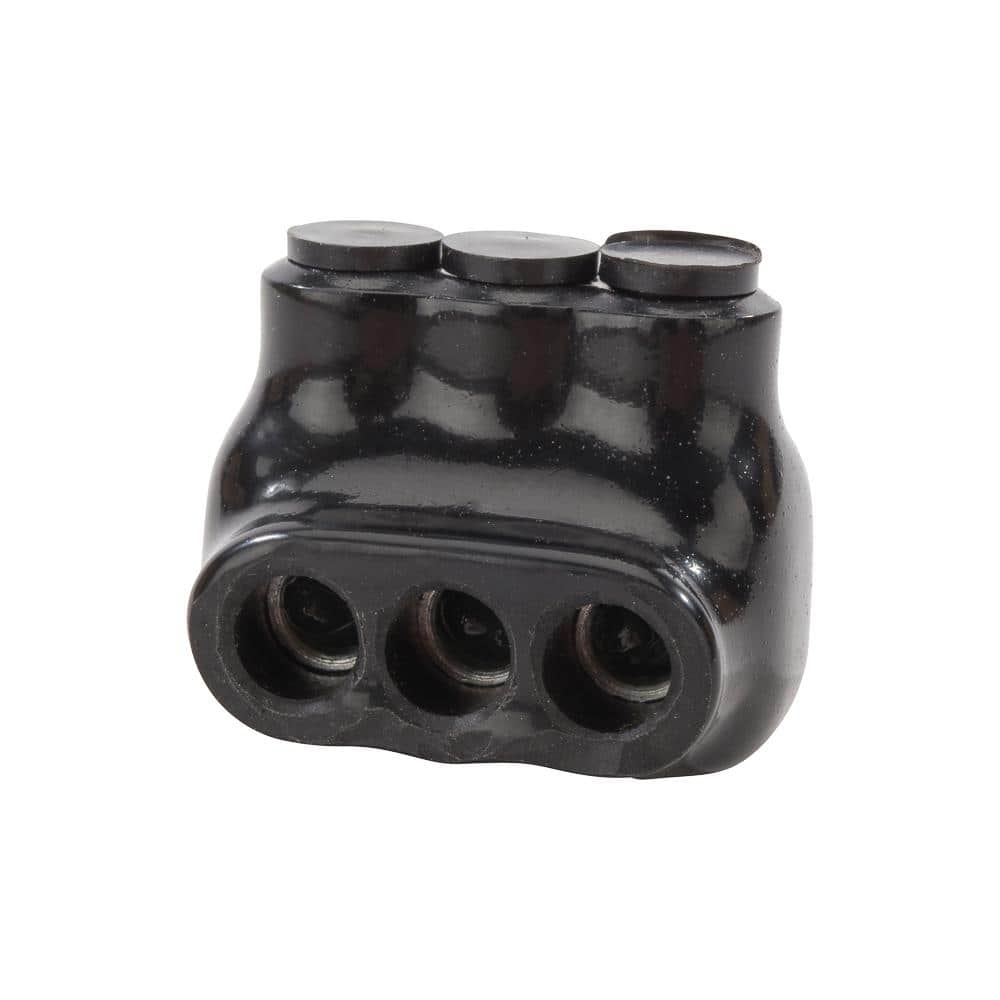
Your layout sounds good, have you considered using DIN rail mount breakers inside of an outdoor enclosure instead of disconnects? DavidPoz does a really good job of describing these types of DIY builds on YT and he has sources listed. Of course the challenge is finding a 15A or 20A breaker that will accept the #2 wire AND the #10 wire on the other side. I have used reducing Ferrules but generally they only go down one size. To make the transition between wire gauges you could use combination 4 to 1 mechanical lugs or maybe Midnight Solar bus bars mounted inside the same DIN rail cabinet.
 
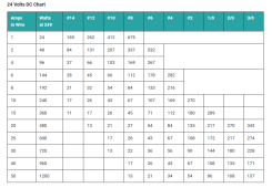
Thank you all for the replies. In answer to the questions about how I came up with 2 AWG wire, I was using a chart here:
1642778618004.png
Since my system is 48V I would get double the distances in the 24V table. I was looking across the 20A row and going out to 135 ft., which would indicate #2 wire would handle the 200 ft (I forgot to double the distance for the round-trip - thank you for the reminder). Other tables on the internet agree with this.

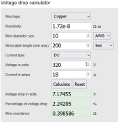
Since you guys mentioned calculators, I looked up a calculator at RapidTables and found a very different answer:
1642778940213.png
As several of you (Bud, rmaddy, Horsefly) said, 10 AWG is fine for a < 3% voltage drop. Other calculators on the internet agree with this.
So why is the tabular method so different from the calculators, and which is right? It would make my day to be able to use #10 or #8 wire the whole way if I can do it safely without too much voltage drop.
 
That first chart you posted is for 24V. But your PV wires will be 320V based on your panel configuration. That makes a huge difference. The higher the voltage the lower the voltage drop.

In other words, your system voltage is irrelevant when determining the wire size for the PV wires because the PV wire voltage is not the same as the system voltage.

Enter 24V into the calculator instead of 320V and you will likely get the same result as the chart.
 
Perfect. Thank you rmaddy. I did what you said - entered 24V into the calculator and got ~5% drop for #2 wire. Thank you for the explanation. I was confusing 48V at the inverter with the voltage from the panels. 10 AWG will work, or 8 for overkill. That makes my long run a lot less complex.
 
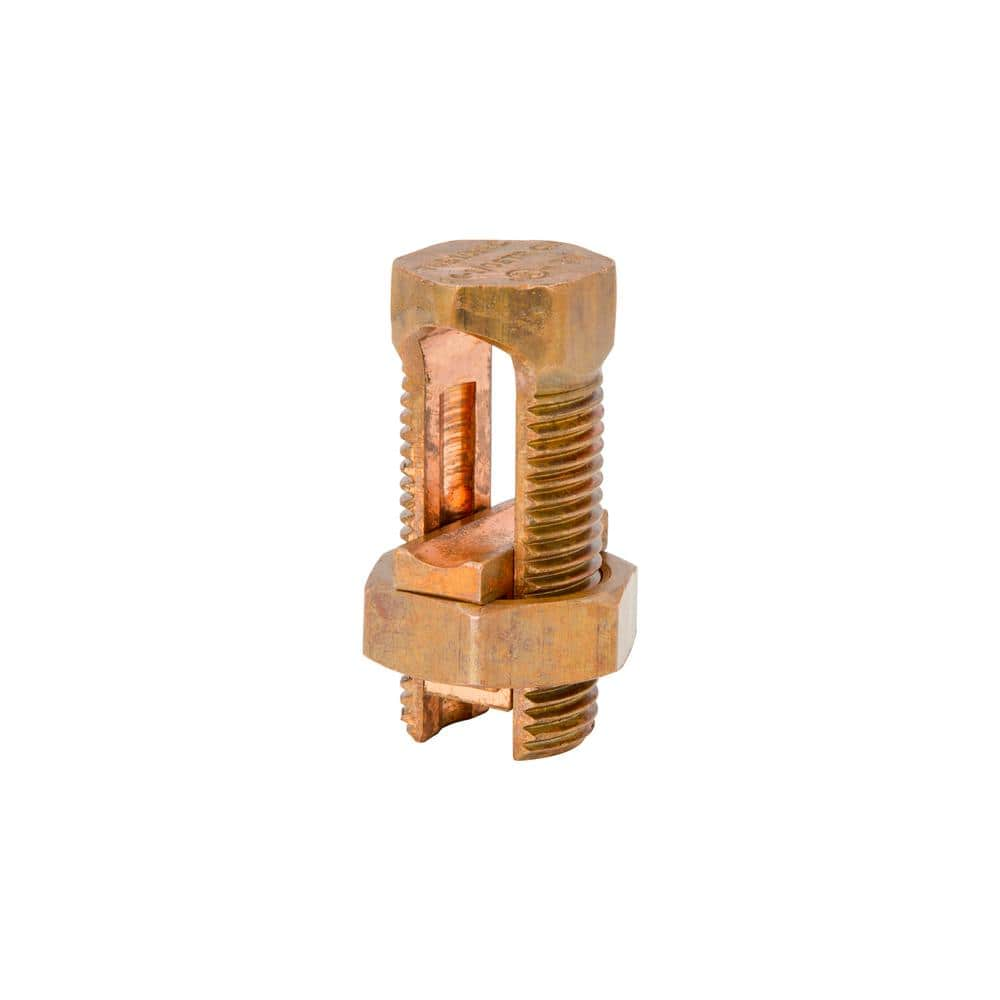
This newbie has a similar story, and similar question. I have a 240'+- run from panels to inverter shed. I bought a 300'+- role of 4awg direct bury, and trenched it in last summer. I have been shoestring budget building a 930 sq ft cabin for 4 years. Now it's time to figure out solar. The cable was a left over from an industrial job, and I couldn't resist it for the price. What is the best way to step down to 8 or 10awg on both ends?
 
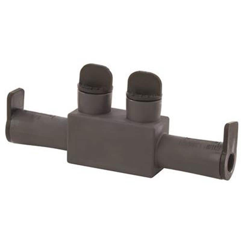
Thanks Hedges. I think the polaris is what I've been trying to find, but will need to enclose it in a weather proof box, at the panel end. Unless there is box that's designed to step up or down.
A very good friend who was also a very good electrician was going to help me get my off grid done this spring, but he passed away. Not that my system means a hill of beans compared to loosing a great friend. Now I'm going to learn the basics, buy the components, and do the grunt work, then hire a capable electrician to hook it up.
 
Ok, then. "Submersible"


What I use are simple gasketed plastic or metal junction boxes. Wires either enter from holes on bottom or through gasketed fittings with glands.
Inside, I use wire nuts or "Ideal" setscrew nuts, for these smaller wires. I've use inexpensive split bolts wrapped in rubber and vinyl tape for heavier wires like 6 awg, AC wiring in my case.

 
Back
Top