diy solar

diy solar

Review my system please

Pick the inverter - then size the wire to 120% of what the inverter draws - then size the fuse to 125% of the wire capacity. This protects the wire from melting and prevents blowing.


This is a sample system from a different thread - I changed it slightly to be like you are doing.


View attachment 215791

I'm not sure how to determine what the inverter draws. 24v, 2500w, 120vac. Probably none of those, knowing me. I'm looking up solar cable and I find 10 and 12 AWG. What am I missing? I'm so close to putting it all together.
 
Ok I'm befuddled. Here what I have so far.
Solar set up

4 100v panels


2 200ah lifepro batteries


Shunt


Circuit breaker


Inverter


Charge controller


Wire gauge and fuse to be determined.
2 sets of Two solar panels wired in a series, connected to system parallel.

I'm pretty sure I'm missing stuff.
 
You've got a pretty good handle on it so far. A little math says:

2500w ÷ 24v = 103a × 125% = 130a, so the 125a breaker in the list is good.

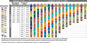
According to the Blue Sea Ampacity Chart, for 130a you'll want 2awg or 1awg if your parts are all within 10ft.

DC_wire_selection_chartlg.jpg

The solar panels in a 2s2p config will be putting out 10.6a so I'd suggest 12awg wire from the Y-splitter at your panels to your SCC. If you wanted to put a breaker from the panels for troubleshooting, a 15a breaker would be good.

When you connect everything together, the B- on the shunt will connect to the battery negative, and your SCC and inverter will connect to the P- of the shunt. The positive from the battery will connect to the SCC and the breaker, then out of the breaker, down the wire, and into the inverter.
 
Just to be clear about the obvious the solar panels might not be within 10 feet. And anything "plugged in" might not be within 10 feet. But I can keep the rest of the system together.
 
Yeah, the panels can be out and yonder, but you'll want to keep the inverter, SCC, and batteries close to each other. The further apart the pieces are, the more copper you need to compensate for voltage drop.

The AC output can go to your distribution panel or however you have that all hooked up in place. You'll want 10awg wire from the AC out to your breaker box.
 
Your equipment list looks great - I bookmarked the battery monitor as a good alternative to the one I posted

I'm not sure how to determine what the inverter draws. 24v, 2500w, 120vac. Probably none of those, knowing me. I'm looking up solar cable and I find 10 and 12 AWG. What am I missing? I'm so close to putting it all together.

2500w/24v = 104amps (it would be twice this at 12v)

I tend to use the windy nation chart - it is 105c welding wire - Pretty much the same chart as @Rednecktek posted.

Welding wire is very fine stranded rubbery sheath - won't bunch when bending a tight turn but won't hold its shape when released
Battery wire is fine stranded - Sheath is a chemical resistant thermoplastic - holds its shape a bit more
THHN has larger strands or is solid - usually multiple layers, PVC and thermoplastic - holds shape very well, but the sheath bunches when bent tight
Solar/PV wire is in a very bendable sheath that is also UV and water resistant so it won't rot away in a few year. It won't allow water inside to corrode the conductors. It is worth the cost if used above ground or not in conduit.

Current carrying capacity of wire is the cross sectional area of the copper - for all types the amount of copper should be the same. The ability to shead heat - solid works best and fine stranded the worst. The happy medium is course stranding like THHN or battery wire.

Wire sheaths are rating for the temperature they can run at and not have issues- for this sort of thing I always buy 105c
Standard THHN like they carry at home depot is typically 90c, but you can get 105c or higher.

Wire sheaths are also rated for voltage blocking - i.e. a 600v rating (pretty standard) will not short to another conductor even if bare unless voltage exceed 600v.

The higher the strand count the more bendable it is. So working in tight spaces it makes sense to use welding wire in my project.

Normally you would also look at voltage drop over length. For our short lengths it seldom matters for anything but the solar array cables. Wire is rated in Ω per 1000ft. To small a wire and the voltage at the other end drops giving you a brownout.

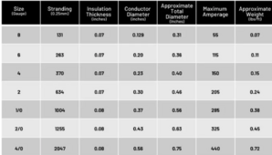
Windy nations' chart
1715955707775.png

There is a lot of good information here.

So you have 105amps from the inverter - if you ever want to go up in inverter size it is simpler to overdo the wire size.

105a * 1.20 = 126amps

So pick a wire - technically 4 awg welding wire will handle the current - but is your wire going to be in free air or enclosed? I tend to figure out my need and go up one size because I don't like the idea of hot wire under any circumstances. So I would pick the 2 awg wire for this project.

If you don't have and don't want to have crimpers for the larger cables (good ones cost $$$) then you can order premade to length cables from someplace like this. This way you know you have good main cables with lugs crimped properly.

Now for the fuse - you can fuse for 20% over 126 amps or fuse for 20% over 150 amps. Because I oversize the wire I tend to fuse for 20% over the size required even though the wire can handle more. If your wires are long get a second fuse and use it at the inverter end. By long in this case I mean more than a couple of feet.

126amps * 1.2 = 151 amps

So in this case I would fuse at 150 amps - it is enough that it will prevent nuisance blows but low enough to blow and protect the wire.

fuse - get a spare or two

Single fuse holder and cap - I personally skip the cap and use rubber ends on all my wires to prevent shorts

Double holder -
so you can use one post with one size wire to the inverter and a second smaller fuse to another device with a smaller wire.

If you add more battery strings or batteries you would also want to add in a class T fuse. The class T has a higher AIC (arc interrupt current)


@Rednecktek recomendation on the wire to the solar panels and the configuration is spot on.

Grounding -

What isn't shown on th diagram posted earlier is the grounding system. For this you assume everything needs to be the same potential. This means 1 and only 1 ground rod driven into the earth at the cabin where the service entrance for power is. If you never had grid power there may or may not be a ground rod.

Ground rods are typically 8 to 10 foot long and driven in vertically. BUT if your soil is very rocky and bedrock is in the way you can put it in at a slant or even horizontal. If you put it in a trench, dig as deep as you can and leave just the top 4" or so above ground to attach a wire.

At any rate - the ground rod runs with bare copper to your electrical panel if you are using one. I see a ground screw on the bottom of the inverter you linked. The wire from the ground rod would need a lug then attach it here. Also you need enough wire to reach your array for grounding the frames of your panels. This wire is connected to only the frames - there should be a screw or clamp for that on each panel. If there are any other metal parts of your electrical systems (like a panel) you would tie that into the ground.

At no point do any of the DC wires, PV wires, or AC wires get tied directly to ground. With the inverter you havbe linked it would seem to be the neutral and ground are tied internally. Would be worth knowing - you can check with a meter and see if that is true - measure voltage across the ground pin (the round one) and the neutral blade (the wider one) if it is zero and doesn't waver they are tied likely tied together. Next test would be to turn things off and measure with the ohm meter the same thing - it should read zero ohms.
 
When you connect everything together, the B- on the shunt will connect to the battery negative, and your SCC and inverter will connect to the P- of the shunt. The positive from the battery will connect to the SCC and the breaker, then out of the breaker, down the wire, and into the inverter.
I hope there are instruction that come with the shunt. Otherwise I'll just have to come back when I get all the parts in front of me. I'm not learned enough to follow what you're describing. But I think working out your instructions will be easier with the pieces in hand.
 
Grounding -

What isn't shown on th diagram posted earlier is the grounding system. For this you assume everything needs to be the same potential. This means 1 and only 1 ground rod driven into the earth at the cabin where the service entrance for power is. If you never had grid power there may or may not be a ground rod.

Ground rods are typically 8 to 10 foot long and driven in vertically. BUT if your soil is very rocky and bedrock is in the way you can put it in at a slant or even horizontal. If you put it in a trench, dig as deep as you can and leave just the top 4" or so above ground to attach a wire.

At any rate - the ground rod runs with bare copper to your electrical panel if you are using one. I see a ground screw on the bottom of the inverter you linked. The wire from the ground rod would need a lug then attach it here. Also you need enough wire to reach your array for grounding the frames of your panels. This wire is connected to only the frames - there should be a screw or clamp for that on each panel. If there are any other metal parts of your electrical systems (like a panel) you would tie that into the ground.

At no point do any of the DC wires, PV wires, or AC wires get tied directly to ground. With the inverter you havbe linked it would seem to be the neutral and ground are tied internally. Would be worth knowing - you can check with a meter and see if that is true - measure voltage across the ground pin (the round one) and the neutral blade (the wider one) if it is zero and doesn't waver they are tied likely tied together. Next test would be to turn things off and measure with the ohm meter the same thing - it should read zero ohms.
So do I wire the panel frames to the ground rod AND wire the inverter separately to the rod? Or will they connect at some point? And I'm using bare copper to do this? Sorry but that seems dangerous. What am I missing here?

I have a meter, so I can check the inverter. I least it seems simple enough.

I'm thinking of the old lightening rods I've heard they used to install on old houses.
 
Next up date

Solar set up


4 100v panels


2 200ah lifepro batteries


Shunt


Circuit breaker


Inverter


Charge controller


Y splitter


12awg for y splitter to scc


fuse to be determined.

I search ground rods. It appears I can just use rebar and copper wire. But until I can be sure I'm listing this as to be determined.


2 sets of Two solar panels wired in a series, connected to system parallel.
12awg wire from the Y-splitter to SCC.
10awg wire from the AC to breaker box
Inverter and solar panels grounded
 
Yeah, the panels can be out and yonder, but you'll want to keep the inverter, SCC, and batteries close to each other. The further apart the pieces are, the more copper you need to compensate for voltage drop.

The AC output can go to your distribution panel or however you have that all hooked up in place. You'll want 10awg wire from the AC out to your breaker box.
I'm not sure about a distribution panel. I've always used a heavy extension cord with several plugins along the length. Just plugged it in on the inverter.

Is the circuit breaker listed the breaker box? That doesn't really make sense, but...?
 
So pick a wire - technically 4 awg welding wire will handle the current - but is your wire going to be in free air or enclosed? I tend to figure out my need and go up one size because I don't like the idea of hot wire under any circumstances. So I would pick the 2 awg wire for this project.

If you don't have and don't want to have crimpers for the larger cables (good ones cost $$$) then you can order premade to length cables from someplace like this. This way you know you have good main cables with lugs crimped properly.

I'm just checking. Am I hearing that I need 2awg to wire the 12vbatteries together into a 24v system?
 
I'm not sure about a distribution panel. I've always used a heavy extension cord with several plugins along the length. Just plugged it in on the inverter.

Is the circuit breaker listed the breaker box? That doesn't really make sense, but...?
Ok, I had it in my head this was a cabin and would have some kind of power distribution system already. My bad, please ignore. You'll only get 15a out of each set of outlets so multiple extension cords and power strips will work fine.

As for the whole fuse vs breaker thing, there are some people that will say "fuse AND breaker EVERY WIRE!" but I'm more of "When you're on a budget and you have to choose, choose the one you can reset in the middle of the night" type of guy.

The ground wire can just be a piece of copper and a length of rebar, they make clamps for doing exactly this that you can get at any hardware store.

Yes, the shunt will come with directions, the main thing you'll need to remember is that the ONLY thing the B- terminal goes to is the battery. Everything else goes on the P- terminal. It'll usually come with the tiny power wire it needs, be gentle with the screws on that, I've torn off more than 1 set of terminals trying to get that screw tight. You'll see what I mean when you open the box.

Grounding is really REALLY confusing, so don't be tempted to fall down that rabbit hole. The screw on the inverter to copper to rebar and call it a day. For some strange reason the world decided to use the electrical term "ground" to refer to something OTHER than the dirt you're standing on.

You've got a pretty good setup listed out, go ahead and hit the "Checkout" button. (y) (y)😁
 
I hope there are instruction that come with the shunt. Otherwise I'll just have to come back when I get all the parts in front of me. I'm not learned enough to follow what you're describing. But I think working out your instructions will be easier with the pieces in hand.

Shunt is easy, look at the diagram I posted, it connects to the negative pole of the battery either before or after the cutoff switch. Then there is a display connected to it. And usually a wire to positive for power.

So do I need a fuse and breaker? I thought a breaker was enough for overload a shorting?

Fuses blow quick in a short condition and breakers trip slow. The MRBF will blow in 0.001s to 0.010 seconds if there is a short.

Unless you get a hydro-mechanical like the midnite solar brand they are affected by temperature. Blow faster in summer and slower in winter. Breakers trip in 0.1 to 3 seconds depending on the short.

If the current is only 2x the size of the fuse or breaker it can take upwards of 10 minutes to blow either. Most times when you have a problem it is a dead short.

At 12v there is a LOT of current involved and the wire can heat hot enough to melt the sheath off in a second or less. This depends on how long the wire is and where the short is. I've done the math for a 6ft piece of wire attached to the battery and connected to a breaker at the other end. If the short is at the battery the fuse blows and nothing else happens. If the short is at the breaker the wire will reach several hundred degrees in 0.5 sec or so. There are lots of ways things can go wrong and we just do the best we can to protect against it.

If you fuse at the battery and have a breaker at the other end you are protected either way.

So, color me in the camp of both - fuse on the battery post and breaker someplace in the line to act as a switch,

But if you get a breaker it needs a box to be mounted into no matter the style - the one @Rednecktek listed is a DIN mount so you would need a small box to put it in. It should come with a 2" piece of DIN rail, but not all do.


So do I wire the panel frames to the ground rod AND wire the inverter separately to the rod? Or will they connect at some point? And I'm using bare copper to do this? Sorry but that seems dangerous. What am I missing here?

I have a meter, so I can check the inverter. I least it seems simple enough.

I'm thinking of the old lightening rods I've heard they used to install on old houses.

The ground from the ground rod ties to the screw on the bottom of the inverter.
You can either run a second ground out to your panels from that same rod or just continue from the inverter to the panels. At the panels it hooks to the panel frames and if there is racking that is metal they are mointed on you connect it to them too.

Your MPPT probably has a place to attach earth ground, most do.

This is NEC and it also makes a lot of sense. It keeps the panel frames and the inverter and anything like a distribution box if that is metal all at the same potential. This means if you touch two things they are at the same potential and they do not shock you. If the wires connected to the panels rub on something and expose the wire and that touches metal you won't get a shock from the frame when you touch it. All at the same potential.

For the ground rod, they sell them at any big hardware store over in electrical. They are typically steel rods clad in copper. You can use rebar for this but it rusts and corrodes away pretty quick if the ground is acidic or if it is a wet climate. Rebar makes a poor conductor as a ground rod because of this. The only time the NEC allows for a ground to involve rebar is if is part of a concrete foundation.

Yes, I know - cabin in the mountains - no inspections - do what you want. But try not to make a shock hazard if it is easy to avoid.

@Rednecktek is right that grounding can be confusing until you understand "ground" isn't the earth. It is a common potential for all equipment so you don't get a shock no matter what you touch.

It is simple if you think through it - if you are barefoot and touch something outside - will it shock you? If you are working on your system and you touch a frame or box will you get shocked? The answer is yes if the cases and frames are not tied to the grounding system back to that rod.

Also if there is a nearby lightning strike with everything at the same potential there is no differential of the potential at the panels than at the cabin. So the strike won't decide to travel through your panel wires and MPPT to ground.


So, yours is a small system - I would attach 10awg bare copper solid wire to the ground rod, then the inverter and MPPT, then along with the PV wire out to the panels. You could also use 12awg to the PV frames.

Your system is simple enough, but I would disagree with Redneck about forgetting it. Personally I would never forget it except on an RV or portable system. And if I were using an RV I think there are short rods or cables to attach to ground points before plugging in at a campground.
 
As an aside - read this post and the reply or all of the thread - @timselectric is our resident expert on all things to do with grounding.

If you get to that point (solar anything is addictive), Tim is also the resident expert on contactors.

 
Ok, I had it in my head this was a cabin and would have some kind of power distribution system already. My bad, please ignore. You'll only get 15a out of each set of outlets so multiple extension cords and power strips will work fine.

As for the whole fuse vs breaker thing, there are some people that will say "fuse AND breaker EVERY WIRE!" but I'm more of "When you're on a budget and you have to choose, choose the one you can reset in the middle of the night" type of guy.

The ground wire can just be a piece of copper and a length of rebar, they make clamps for doing exactly this that you can get at any hardware store.

Yes, the shunt will come with directions, the main thing you'll need to remember is that the ONLY thing the B- terminal goes to is the battery. Everything else goes on the P- terminal. It'll usually come with the tiny power wire it needs, be gentle with the screws on that, I've torn off more than 1 set of terminals trying to get that screw tight. You'll see what I mean when you open the box.

Grounding is really REALLY confusing, so don't be tempted to fall down that rabbit hole. The screw on the inverter to copper to rebar and call it a day. For some strange reason the world decided to use the electrical term "ground" to refer to something OTHER than the dirt you're standing on.

You've got a pretty good setup listed out, go ahead and hit the "Checkout" button. (y) (y)😁
I'll be careful of the shunt. Thank you.
 
Solar set up


4 100v panels


2 200ah lifepro batteries


Shunt


Circuit breaker


Inverter


Charge controller


Y splitter


12awg for y splitter to scc


2 Breaker box (one for panels, one for inverter)


10awg wire breaker to inverter


Ground wire


Ground rod


Fuse, holder, cap


Breaker from panel to setup

Battery cable 2sets


2 sets of Two solar panels wired in a series, connected to system parallel.

12awg wire from the Y-splitter to SCC.

10awg wire from the AC to breaker box

###
Side note: Ok so I would prefer an AIO. But I don't have that amount all at once. Sorry.
There's a lot of info hear that's over my head. But, I'll buy the parts and figure it out. It takes me about 6 months or more to buy all the parts on this list. I'm assuming emergencies, unintended purchases. If I bite the bullet AND I'm lucky, Maybe 2 months.
I recognize BatterycablesUSA.com and Mouser.com are good websites. I just use one platform out of ease and habit. If it's all the same I'd like to use Amazon. If not let me know.
###


I'm hoping this is my final check in. If there's anything I don't need, or can be upgraded as few months after setup. Now the time to grant me mercy. Lol

By the way, all this assumes my batteries are not ruined. I still haven't had a chance to charge them up. I have about 7-9 generator hours a day with my gas rationed. So I'm waiting until I get paid to buy the extra gas for a continuous charge.
 
As an aside - read this post and the reply or all of the thread - @timselectric is our resident expert on all things to do with grounding.

If you get to that point (solar anything is addictive), Tim is also the resident expert on contactors.


Thanks for the tip. I'll read up.
 
Back
Top