diy solar

diy solar

Ripple in Double Conversion UPS

I didn't mean double-conversion causing reversal (but come to think of it, it will.)

I meant power factor lower than 1.0; there are two kinds: wave shape, like rectifier/capacitor taking gulps of current off the top. No reveral there. Other kind is inductive or capacitive load a phase shift between sine wave current & voltage, where current is same polarity voltage part of a phase (discharge) and opposite polarity part of a phase (recharge.)

As for double conversion:
If charging source is off, battery provide rectified sine wave discharge.
If charging source is on, but not synchronized with AC output, there is rectified sine wave charging, and rectified sine wave discharging. Sum of those two currents will have polarity reversal. Charge and discharge.

If you have DC coupled SCC and a single phase inverter, there will also be polarity reversal of current.
 
I would think it could potentially double the magnitude. AC in and AC out, vs. DC in.
Well, not quite double. One is constant current, average of load, with load swinging from zero to peak. The other is peak charge followed by peak discharge.

I don't know if 120 Hz micro charging/discharging is a problem for either chemistry or not. Probably not a good thing, unless it removes sulphation from lead-acid. But maybe not optimum frequency for that.

I think spinning generators are pretty good about power factor, also have rotational inertia and energy storage large compared to a cycle of AC. But there could be some frequency jitter during load transitions.

Again all just by reasoning on it.

Could take some measurements with a motor-generator, cutting off input to coast. Or monitoring DC input current while operating.
 
I don't know if 120 Hz micro charging/discharging is a problem for either chemistry or not. Probably not a good thing, unless it removes sulphation from lead-acid. But maybe not optimum frequency for that.
The PWM frequency from active power factor correction, SMPS inside AC charger, and the PWM in the inverter can potentially add kHz frequency ripple
 
Nice! That's the closest to understanding any of us have found so far I think. Didn't think about how the inverter would have a ripple type effect on the draw.
The crux of the question with this double conversion is - "how does constantly drawing and re-charging right around a given point - say 70% charge - affect the chemistry?" And "is it better to have some more dramatic swings to keep the chemistry..um.. "exercised"?" The Victron charger will do that every 7 days automatically and frequent one hour power outages will too. Adding some solar may be helpful for the same reason. A bit more "exercise' of charge/discharge and less "ripple" which I'm now taking to mean tiny variations around a charge level.
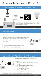
When Victron is talking about ripple they are talking about this, because if ripple is kept low the Victrons can surge significantly above their rated power.


Key to avoid problems - keep resistance low, adequate sized battery and cabling etc Screenshot_20240105_181239_Samsung Notes.jpg
 
Victron put out some good stuff.
Long before I ever thought of measuring it. The Midnight guys (while they were Trace) may have also.


I'm going back to the OP's statement about "double conversion UPS" having to worry more about ripple. I can only guess this is because the AC->DC converter/charger is always on, vs AC going directly to the load through a transfer switch like a standby UPS.

How is this any different from a float-stage charger on an SLA battery? I have trouble believing mV of ripple (at whatever frequency) actually affect a battery in any real way.

Related but not quite the same problem, Lithium chemistry batteries don't "like" to be kept at 100% full forever, which is exactly the pattern for a UPS. It's one reason (well, mostly cost, if I'm being honest) I went with SLA AGM batts when I cobbled together my DIY UPS from discrete components.
You nailed it as far as MY question. To make it more generalized- Is there anything special to be concerned about with an online double conversion UPS vs the transfer-switched approach? Secondary is LFP vs LA in double conversion.

I was not personally alert or concerned about this hypothetical "ripple" before I was warned on a thread here that it might be a concern. Again, I am now convinced that it's a complex and subtle issue that may (or may not) be relevant but is certainly not a commonly known fatal mistake.

As far as where the charge state "sits" most of the time, yes, LA is easy -keep it topped! But I have come to understand that by setting an appropriate "float" or "storage" voltage on our SCC/whatever charger, we can control whether an LFP battery is actually gaining (and losing) charge or just passing the current on to the loads, thus avoiding pointless cycling when there is grid power or solar/whatever available. I believe that off-grid solar LFP based systems generally work this way with no transfer switching involved. If a 12V pack's resting voltage is 13.3x then setting the storage stage somewhere around 13.3 will mean that no current is pulled until and except when the load comes online and then it will mostly or completely pass through as needed if available.

Right now, my 15amp Victron charger is set for 13.35 in the storage stage. It shows 3.6 amps of draw while the battery voltage seems stable at 13.35V. My BMS shows 13.27 with it's estimated charge level of 60%. My not so well-matched cells vary from 3.318-3.321

My interpretation is that I'm seeing very little cycling here - though at the expense of having a reduced capacity available if power goes off. I might bump the charge storage stage V up a bit to see if I can keep it closer to 80% charge. But really, I need to get a shunt installed first to have a better idea.

So that's my real world concern and understanding in practice now.

It's cool to see the EE guys here sorting some of this out ! It's mostly over my head but I appreciate the orientation and think that a good discussion online benefits the community at large, not just one person's concern.
 
Last edited:
You nailed it as far as MY question. To make it more generalized- Is there anything special to be concerned about with an online double conversion UPS vs the transfer-switched approach? Secondary is LFP vs LA in double conversion.
(I am not an EE but I do spend a lot of time looking at various metrics for complex software systems. Also I haven't looked at the schematics, so take this with a grain of salt. FWIW this question can be resolved very quickly if we just find a power engineering PhD student to find the relevant paper, skim for 30 min and give us a summary.)

Keep in mind that you may be applying ideal power source assumptions when analyzing it. And your measurement equipment (the shunts) may not sample quickly enough to detect ripple. So the measurement deficiencies may confirmation-bias/line up with your incomplete assumptions

For instance if the shunt integrates(as in "accumulate it") net DC current over 0.5s I'm pretty sure you'll never see any ripple. The load could draw a few micro-amp-hours from the battery, then the charger pushes that back in, and that still nets to 0. From the shunt on the output of the charger's, it is impossible to know how much of the current went into the battery. Only a shunt on the battery has a chance, if it samples quickly enough.

Transfer switch approach seems seems much easier to eliminate the possibility of charge/discharge ripple on the battery. In that approach, to achieve the lowest transfer time the inverter should be kept spun up but disconnected from the load. This should be a fairly low idle draw that is independent of the load being supported. Some cleverness will need to be done to simultaneously avoid rippling the battery & providing the idle power to the inverter. Maybe a transfer switch on the DC side too to supply the inverter in standby mode directly from the charger without also having the battery in the circuit.

If you have online double conversion, where there are no AC relays and switching from grid to inverter power, then you have to start worrying about the battery/inverter/charger all pushing and pulling against each other. And you can't simplify this away by isolating the battery, because that would may increase the transfer time.

Now if you do something like constantly cycle the battery (EG, it's never in float, you are always either off charger or charging at a high enough current to serve any inverter load that comes on), you can see that ripple is impossible to happen. But you are putting cycles on the battery.

If a 12V pack's resting voltage is 13.3x then setting the storage stage somewhere around 13.3 will mean that no current is pulled until and except when the load comes online and then it will mostly or completely pass through as needed if available.
This makes sense for ideal power supplies but real power supplies do not react instantaneously. I would expect a LFP battery to be stiffer than a charger/power supply, since the batteries are natively providing some voltage without the need for fancy circuitry.

The charger is a switched-mode power supply (SMPS) and it literally synthesizes the output voltage / current with a controller governing the switching/pumping of power across itself. This will need to adjust as the demand increases/decreases.

So suppose battery is in float. UPS load is idle. The SMPS only has to pump a small amount of energy through to maintain the float voltage (parasitic losses + the idle draw of the UPS inverter).

For concrete scenario, think of server sitting idle waiting for a request (5W). And then it gets sent a request that requires running some program on the GPU (200W). On 12V battery that is 0.5A in the initial state and 16A in the second state.

Going from 0.5A to 16A on the battery is instant, because it's a battery and can react with just chemistry. On the SMPS, there will be some electronic logic involved.

Now, if all we have to worry about with ripple is this kind of transient, then maybe it's less important to worry about.

---
To sort of summarize. I think ripple is intrinsically a challenge to the simplified ideal charger / power source model (intellectual challenge - it does not happen if you idealize the components enough). And then beyond that, I think there are multiple kinds of potentially relevant ripples.

1) Above, I mentioned one that operates at slow time scales and when the system switches between different steady state current draw.

2) There is also the faster timescale of the multiple SMPSs in the system. The charger is a switch mode devices, and the inverter is also a switch mode device. And in steady state with no change in current draw from the load on the output of the UPS, the inverter will be pulling from the charger's output at a khz frequency, and the smps reactively adjusts how it pushes back, also at a khz frequency. The charger is effectively a parallel power source to the battery so we would need to do circuit analysis or simulations to see how the two share the high frequency changes in load.

If there is good filtering on the charger, maybe it can supply more of the power than the battery.
 
One thought to avoid ripple:
Two battery banks.
Charger is charging bank A.
Inverter drawing on bank B.
At some point (80% soc?):
Both banks brought online with Inverter, and then bank B is disconnected and charged.
You are then cycling between 80%-100%, which is better than ripple.
 
Interesting idea, though I think you can get the same property with a single battery. That was alluded to in this part of my post:

Now if you do something like constantly cycle the battery (EG, it's never in float, you are always either off charger or charging at a high enough current to serve any inverter load that comes on), you can see that ripple is impossible to happen. But you are putting cycles on the battery."

I don't think you need any DC switching either which would add cost to do correctly under load, just turn on/off the charger programmatically.

You are then cycling between 80%-100%, which is better than ripple.
Can you explain or cite a source for why long cycles are better than ripple?
 
Can you explain or cite a source for why long cycles are better than ripple

I think the problem is when cycling between charging/discharging (ripple around fully charged).


"In addition, many studies have shown that the high-frequency current ripple could trigger the deposition of lithium metal on the surface of the negative electrode and cause capacity degradation even generating an internal short circuit, especially in harsh low-temperature environments"


"Just papers that are publicly available and indexed by Google, which unfortunately isn't a lot. You might be able to find more in a good pay-walled research index. FYI, in addition to the effects described above, in some chemistries, local polarization of the electrolytes can occur. This reduces the reaction rate, reducing power output, and may increase effective resistance and power losses. Also, with a Li-ion battery, I believe you always need to be concerned about minimizing how often you change the polarity of the current, i.e., minimize the number of transitions from a charging state to a discharging state, because just about all Li-ion batteries suffer from capacity fade as they are charged and discharged. As long as the ripple is smaller than the DC, then you will be either charging or discharging and not cycling between the two, so this would not be a problem."
 
Last edited:
...
As for double conversion:
.........
If charging source is on, but not synchronized with AC output, there is rectified sine wave charging, and rectified sine wave discharging. Sum of those two currents will have polarity reversal. Charge and discharge.

If you have DC coupled SCC and a single phase inverter, there will also be polarity reversal of current.
There it is. Next question is about magnitude of effect (relative to power?) and cycle depletion on battery. Is it significant?
 
...
If you have online double conversion, where there are no AC relays and switching from grid to inverter power, then you have to start worrying about the battery/inverter/charger all pushing and pulling against each other

...
One of many good nuggets.

I think there are multiple kinds of potentially relevant ripples.

1)......one that operates at slow time scales and when the system switches between different steady state current draw.

2) There is also the faster timescale of the multiple SMPSs in the system. The charger is a switch mode devices, and the inverter is also a switch mode device. And in steady state with no change in current draw from the load on the output of the UPS, the inverter will be pulling from the charger's output at a khz frequency, and the smps reactively adjusts how it pushes back, also at a khz frequency. ...
Great stuff. So ripple is likely creating a discharge/recharge effect and it's much finer than we can measure with charge level/shunts and it's likely happening on a couple of scales at once.
If there is good filtering on the charger, maybe it can supply more of the power than the battery.
Well this is a possible lifeline for me using a charger featured as a "charger/power supply" I guess I need to read that Victron stuff and see if there's any real hope that they offer some compensation for the effect in their circuit design. Could ask on their forum also.

Thanks mucho. It's challenging to keep up with all the info you guys are bringing forward but worth it. I may conclude that I need a transfer switch. Problem is that in this case I am also making use of the power conditioning I get from double conversion.

I'm sticking with the gear I have in this situation. But another system might be wiser to spend more and get an Inverter/charger.

Practical question that remains is: "how much does this constant push-pull matter to LFP life? Is it accumulating as a serious effect OR , due to scale and/or the chemically friendly nature of charging right around the sweet spot keeping this ripple effect small on the overall battery life?

I've got thousands of cycles to use up one way or another in the next 10 years life that I would like to get out of the battery. So the effect may likely be tolerable. I wonder if anybody has some years of experience with a double-conversion LFP?
 
I think the problem is when cycling between charging/discharging (ripple around fully charged).
Implying that cycling around 80% or perhaps 60% might not be as destructive?
........As long as the ripple is smaller than the DC, then you will be either charging or discharging and not cycling between the two, so this would not be a problem."
With no idea about the magnitude of the ripple, I'm still taking this to mean that the smaller the load on the inverter, the more chance ripple is dominating. But hard to know what is small.
 
There it is. Next question is about magnitude of effect (relative to power?) and cycle depletion on battery. Is it significant?

I don't understand complex subjects like chemistry. Or women.
Only simple, logical things like electromagnetic interference and rocket science.
 
Great stuff. So ripple is likely creating a discharge/recharge effect and it's much finer than we can measure with charge level/shunts and it's likely happening on a couple of scales at once.

There's several of these effects that can be faster than what a shunt would be able to see.

It's not physically impossible to implement, you just have to be aware what it can / cannot see.

On a related context, smart meters from the power company have a native sampling rate in the kHz or higher and they can accumulate the data in different ways. In the most basic configuration (energy every 15 min, maybe also peak power) small scale import/export etc from the house will not show up. They can be configured to gather more stuff, IE they can also look at spectral power quality so they can bill large users on poorly corrected power factor. And in some places they also want to find unapproved equipment connected to the grid, and the higher sampling rate gives them more chances.

I did some quick digging and I don't see much discussion of the sampling rate on battery shunts or how well they see high frequency data. A few on DIY battery forums.

I've got thousands of cycles to use up one way or another in the next 10 years life that I would like to get out of the battery. So the effect may likely be tolerable. I wonder if anybody has some years of experience with a double-conversion LFP?
If the LFP datasheets are believable (probably OK, since the chemistry is 10 years old now) then you'll hit calendar age long before you run out of cycles on most applications.

If I was doing this I'd probably be happy personally with measuring the temperature of the battery when I set it up initially, and maybe having a game plan for monitoring the health of the cells. Maybe charge to top and then do discharge test to see how much capacity is left.
 
Implying that cycling around 80% or perhaps 60% might not be as destructive?
That's what I'm guessing. All the ions are still flowing in the same direction. Just speeding up and slowing down. Not as bad as ions crashing into each other as they reverse direction.

Note: the discussion was for batteries in EV. Home might be a much more benign environment.
 
That's what I'm guessing. All the ions are still flowing in the same direction. Just speeding up and slowing down. Not as bad as ions crashing into each other as they reverse direction.

Note: the discussion was for batteries in EV. Home might be a much more benign environment.
Yes! Magnitude relative to draw hopefully makes this concern more academic than worrysome for average DIYer.
 
If I was doing this I'd probably be happy personally with measuring the temperature of the battery when I set it up initially, and maybe having a game plan for monitoring the health of the cells. Maybe charge to top and then do discharge test to see how much capacity is left.
Yes, of course. The most accurate answer to the applicability or relevance of this phenomenon for DIY double-conversion UPS is going to be real world results as measured by capacity loss. Along with reference for where the pack has been hovering in the charge state for given system. Some folks are going to optimize for maximum available backup power and stay close to the top while others will prefer to (hopefully) avoid excessive wear and hover around a more compromised charge state. I'll be fine with 75% of capacity available, which is a guess on a decent compromise.

With this or my other RV LFP system I have to constantly remind myself that while cycle awareness is needed to some degree, that even if the battery doesn't truly age out, it will very likely be fully antiquated tech in ten years. It's a tricky game finding the sensible approach for a finite cycle life that is still likely to be more than needed in many situations. In my UPS application, full cycling may happen 20 times a year! Including testing.

The tricky part about cycle testing with LFP chemistry is to detect early enough before it's grown to "stage 3" - so to speak. Even if ripple is degrading at 400 cycles per year, it might not show up in the first year. Then again, that's still close to ten years before dropping to 80%. And that's IF 24 hours of ripple creates over 1 cycle.

The bigger concern is some sort of extreme chemical effect as mentioned but seems that there would be some sign of that on the interweb (beyond research papers ) if dramatic.

Hmm. Where are the people who have been running an LFP double conversion system for years ? Must be a few out there.
 
Back
Top