• Have you tried out dark mode?! Scroll to the bottom of any page to find a sun or moon icon to turn dark mode on or off!

diy solar

diy solar

Trying to deeply investigate LED pulsing flickering with HF off-grid inverters

fmeili1

Solar Addict
Joined
Jan 19, 2022
Messages
590
Location
Arizona, Mohave County
After some research, it looks like that the problem with LED pulsing/flickering is well known. It's seen on nearly all brands and models of HF pure sine off-grid inverters.

I'm trying to fundamentally understand the problem and find possible solutions. Here are some of my thoughts.

Let's assume that
  1. the inverters are not broken and working as designed
  2. the firmware is more or less finally optimized in regards of the PWM control loop to drive the H-Bridge
  3. the external wiring of the whole system is nearly perfect
It turns out that the working principle of these inverters has a general weakness to stabilize the output voltage under ANY load situation (LF inverters are a different story and they are more robust about "dirty" loads).

Here are some observations which I've googled and some of them, I've observed by myself.

  1. The pulsing frequency is usually in the range of 3-7 Hz
  2. The pulsing gets worse if the inverters have low load and nearly disappears under high load
  3. A specific device (load) connected to the inverter may start or increase the LED pulsing (connected on the same phase). e.g. specific laptop power supplies, 3D printers, etc. Without using these 'dirty' loads, there is nearly no LED pulsing
  4. Some are able to hide the LED pulsing by using "better" LED bulbs - this workaround is not a possible for all these fixed build in LED's in a house, e.g. in ceiling fans, etc. In general, this is not a solution, just a workaround because the inverter still produces pulsing on it's AC output
  5. If LED's are dimmable, the pulsing gets worse if they are dimmed down
  6. ...
From my understanding, an inverter PWM control loop can't never be perfect and depending on the load type, it tries to stabilize the output voltage. Under some circumstances, some loads my result in an oscillating control loop which causes the unstable output voltage (which causes the LED flickering). An analogy may be a HiFi stereo amplifier which needs to be perfectly trimmed to the used speaker to work perfect. An inverter should work with any type of load and could in principle not be trimmed perfect for any load situation.

But I still hope that there may be possible solutions to solve or at least reduce the root cause of the LED pulsing. Maybe there could be a specific type of filter installed in the power line to the "dirty" loads to reduce the oscillating interaction between the inverter and the load.

I've made a simple test with a self made online double conversion UPS which I've connected between the receptacle and the "dirty" loads which interfere with the inverter to make them pulse. In my case an old slot machine and a 3D printer. In both cases the LED pulsing was completely gone after decoupled the dirty load from the inverter (via this UPS). But this is not really a solution because it's too expensive to isolate any "dirty" load with it's own online double conversion UPS.

To find a good filter (if possible) to reduce the interferences between a "dirty" load and an inverter, I think it's necessary to understand the nature of the distortion/oscillation problem.

I've already tried two simple filters (filter1, filter2) but both showing no positive effect about this problem.

My theoretical electrical knowledge is a bit rusty, maybe someone could shed some light in this problem and possible (filter) solutions. I think first it's required to understand the nature of the "noise" (oscillating) before a possible filter type may be selected.

In this graphic you can see the visual difference in SA of the output voltage with the dirty load enabled and at about 9:50am without the dirty load (from 9:50am the LED's don't flicker anymore). SA is not really the right tool here, because it's way too slow to "see" all fast voltage fluctuations - but even here it's visible and I guess with a higher time resolution it would show it much worse.
1703268219212.png
 
After some research, it looks like that the problem with LED pulsing/flickering is well known. It's seen on nearly all brands and models of HF pure sine off-grid inverters.

I'm trying to fundamentally understand the problem and find possible solutions. Here are some of my thoughts.

Let's assume that
  1. the inverters are not broken and working as designed
  2. the firmware is more or less finally optimized in regards of the PWM control loop to drive the H-Bridge
  3. the external wiring of the whole system is nearly perfect
It turns out that the working principle of these inverters has a general weakness to stabilize the output voltage under ANY load situation (LF inverters are a different story and they are more robust about "dirty" loads).

Here are some observations which I've googled and some of them, I've observed by myself.

  1. The pulsing frequency is usually in the range of 3-7 Hz
  2. The pulsing gets worse if the inverters have low load and nearly disappears under high load
  3. A specific device (load) connected to the inverter may start or increase the LED pulsing (connected on the same phase). e.g. specific laptop power supplies, 3D printers, etc. Without using these 'dirty' loads, there is nearly no LED pulsing
  4. Some are able to hide the LED pulsing by using "better" LED bulbs - this workaround is not a possible for all these fixed build in LED's in a house, e.g. in ceiling fans, etc. In general, this is not a solution, just a workaround because the inverter still produces pulsing on it's AC output
  5. If LED's are dimmable, the pulsing gets worse if they are dimmed down
  6. ...
From my understanding, an inverter PWM control loop can't never be perfect and depending on the load type, it tries to stabilize the output voltage. Under some circumstances, some loads my result in an oscillating control loop which causes the unstable output voltage (which causes the LED flickering). An analogy may be a HiFi stereo amplifier which needs to be perfectly trimmed to the used speaker to work perfect. An inverter should work with any type of load and could in principle not be trimmed perfect for any load situation.

But I still hope that there may be possible solutions to solve or at least reduce the root cause of the LED pulsing. Maybe there could be a specific type of filter installed in the power line to the "dirty" loads to reduce the oscillating interaction between the inverter and the load.

I've made a simple test with a self made online double conversion UPS which I've connected between the receptacle and the "dirty" loads which interfere with the inverter to make them pulse. In my case an old slot machine and a 3D printer. In both cases the LED pulsing was completely gone after decoupled the dirty load from the inverter (via this UPS). But this is not really a solution because it's too expensive to isolate any "dirty" load with it's own online double conversion UPS.

To find a good filter (if possible) to reduce the interferences between a "dirty" load and an inverter, I think it's necessary to understand the nature of the distortion/oscillation problem.

I've already tried two simple filters (filter1, filter2) but both showing no positive effect about this problem.

My theoretical electrical knowledge is a bit rusty, maybe someone could shed some light in this problem and possible (filter) solutions. I think first it's required to understand the nature of the "noise" (oscillating) before a possible filter type may be selected.

In this graphic you can see the visual difference in SA of the output voltage with the dirty load enabled and at about 9:50am without the dirty load (from 9:50am the LED's don't flicker anymore). SA is not really the right tool here, because it's way too slow to "see" all fast voltage fluctuations - but even here it's visible and I guess with a higher time resolution it would show it much worse.
View attachment 184553

Would a single resistive load (like an incandescent light bulb) somewhere in the system do the trick?

Maybe like a 25 watt draw?
 
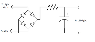
A lot of LED light bulbs have no energy storage capacitors so they can be made cheaper. This makes LEDs respond to voltage variations very quickly unlike incandescent bulbs that have inherent energy storage capacitor in the form of hot filament. You can try this simple circuit to add capacitance to Edison base type LED filament bulbs to smooth out these voltage ripples.

LED-RC-filter-circuit.png
Resistor and capacitor values depend on LED bulb power rating. For 5W LED bulb 1kOhm 5W rated resistor can be tried with 100 microfarad 200V capacitor. There is math involved calculating these values precisely but it escapes me right now.

Edit: I just tried few bulbs and some very cheap ones work while more expensive dimmable type work with 200 ohm resistor. Dimmable 120Vac LED bulbs work fine at 50Vdc at about half brightness. I used 300uF 200V cap and it adds slow light fade effect when power is removed. I tried loading my 800W inverter with a heat gun on low setting and there is no flicker at all.
 
Last edited:
This seems to be a classics case of an underdamped system. When the load is high, the PWM controller has to dump enough power into the pulse to not let the voltage drop, but when you drop the load near zero, it can't get the pulse width small enough to prevent overshoot. The number of inverters could also be an issue, since the latency between them has the effect of limiting the lower end of the PID controller bandwidth.

Can you test with just a single inverter? It would be interesting to see how much load makes the problem go away with all of the inverters and with just one.

A capacitive load would be better than a resistive load, but I don't know of a large capacitor that will work with AC.

You can calculate the frequency response of an RC circuit here. You don't need to hit the exact frequency of you fluctuations. You just need to ensure that the filter doesn't significantly reduce 60Hz.

I don't think standard AC power filters are going to be much use, since they're designed more for high frequency noise.
 
A lot of LED light bulbs have no energy storage capacitors so they can be made cheaper. This makes LEDs respond to voltage variations very quickly unlike incandescent bulbs that have inherent energy storage capacitor in the form of hot filament. You can try this simple circuit to add capacitance to Edison base type LED filament bulbs to smooth out these voltage ripples.

View attachment 184591
Resistor and capacitor values depend on LED bulb power rating. For 5W LED bulb 1kOhm 5W rated resistor can be tried with 100 microfarad 200V capacitor. There is math involved calculating these values precisely but it escapes me right now.

Edit: I just tried few bulbs and some very cheap ones work while more expensive dimmable type work with 200 ohm resistor. Dimmable 120Vac LED bulbs work fine at 50Vdc at about half brightness. I used 300uF 200V cap and it adds slow light fade effect when power is removed. I tried loading my 800W inverter with a heat gun on low setting and there is no flicker at all.
In case it would not be possible to find a solution to filter the "dirty" loads out of the system to solve the root cause of the LED pulsing, I may need to do such a modification for each pulsing LED in the house...
 
  1. The pulsing frequency is usually in the range of 3-7 Hz
  2. The pulsing gets worse if the inverters have low load and nearly disappears under high load
You are spot on regarding pulsing frequency.

Another point I would like to add is that for my hardware, LXP SNA 5k,
pulsing only occurs when I have enabled PV + AC Hybrid setting ('Take load together').
I haven't noticed any pulsing at all with purely battery + PV offgrid modes.
Regarding second point, pulsing was most noticeable at EOD with Solar diminishing.
Let's hope with enough detailed information, someone finally figures out a way for this problem.
 
This seems to be a classics case of an underdamped system. When the load is high, the PWM controller has to dump enough power into the pulse to not let the voltage drop, but when you drop the load near zero, it can't get the pulse width small enough to prevent overshoot.
That sounds like a good explanation for the problem. Since almost all HF inverters seem to have this problem (more or less), it looks like that there is a principle limit in the PID controller that should not be exceeded. Otherwise, the manufacturers could simply increase the damping of the PID controller. The selected setting is probably a compromise for the "usual" application situations.

The number of inverters could also be an issue, since the latency between them has the effect of limiting the lower end of the PID controller bandwidth.

Can you test with just a single inverter? It would be interesting to see how much load makes the problem go away with all of the inverters and with just one.
Good idea! I will try this over the next couple of days.

A capacitive load would be better than a resistive load, but I don't know of a large capacitor that will work with AC.

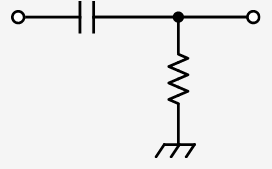
You can calculate the frequency response of an RC circuit here. You don't need to hit the exact frequency of you fluctuations. You just need to ensure that the filter doesn't significantly reduce 60Hz.
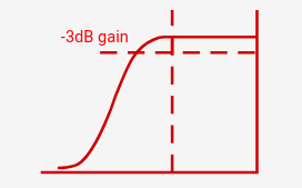
Do I understand correctly that you are suggesting a high-pass filter that has its cutoff frequency at, e.g. 15 Hz and then putting this filter in the power wire (between L and N) of the "dirty" load? Something like this:

1703344243654.png-----1703344262573.png

With R=330kΩ and about C=33nF it would result in a filter with a cutoff frequency of 14.6 Hz.

I don't think standard AC power filters are going to be much use, since they're designed more for high frequency noise.
understand
 
Question, why don’t the lights flicker when running my cheap inverter generator but they do when using a HF battery inverter? Assume they run under the same principles. I connect them both the same way through a TS without G/N bond at source, but in panel.
 
Last edited:
You are spot on regarding pulsing frequency.

Another point I would like to add is that for my hardware, LXP SNA 5k,
pulsing only occurs when I have enabled PV + AC Hybrid setting ('Take load together').
I haven't noticed any pulsing at all with purely battery + PV offgrid modes.
Regarding second point, pulsing was most noticeable at EOD with Solar diminishing.
Let's hope with enough detailed information, someone finally figures out a way for this problem.
I have not yet installed the solar PV panels (time constraints). So the system runs now in test mode just with batteries, recharged from the grid if they gets empty. So I only can tell for battery mode for now and here I have the pulsing LED, just when turning on one of my "dirty" loads. Looking forward how the pulsing situation may change again after the PV panels are installed.
 
That sounds like a good explanation for the problem. Since almost all HF inverters seem to have this problem (more or less), it looks like that there is a principle limit in the PID controller that should not be exceeded. Otherwise, the manufacturers could simply increase the damping of the PID controller. The selected setting is probably a compromise for the "usual" application situations.


Good idea! I will try this over the next couple of days.


Do I understand correctly that you are suggesting a high-pass filter that has its cutoff frequency at, e.g. 15 Hz and then putting this filter in the power wire (between L and N) of the "dirty" load? Something like this:

View attachment 184709-----View attachment 184710

With R=330kΩ and about C=33nF it would result in a filter with a cutoff frequency of 14.6 Hz.


understand

The RC filter would be the same as the picture in post #4, without the rectifier, which means you don't have + and - terminals, since it's AC. The capacitor needs to go across the wires. The problem is that large capacitors are generally electrolytic capacitors, which blow up if they're reverse biased, so that's not going to work. You don't want to connect the resistor to ground, since that would induce ground currents.

The resistor is inline for an RC filter, so you want to minimize it. You may even be able to eliminate it and utilize the small internal resistance in the device. The resistor just controls how fast the capacitor can charge and discharge.

A better idea might be using an LR filter. The inductor is going to be inline, so it needs to be able to handle the current, which is a problem. You could probably test it using an autotransformer. I have never looked into how a low-frequency inverter works, but I assume the large coil that they have serves a similar purpose.

All of these filters also change the phase, which might or might not matter, but if you put a large inductor on only one phase, it could significantly put that phase out of phase with the other phase (that's alot of phases), which could be a problem for inductive loads.

FWIW, switching voltage regulator work on essentially the same principle and have very specific requirements for the RLC filters required to maintain a stable signal over the range of voltages.

All that said, figuring out the amount of load that you need to get past the unstable point should be the first step. If it's not very much, it would likely be easier to just figure out something useful to do with that load and sacrifice some efficiency by keeping a small load on all the time.

I seems kind of silly on the surface, but maybe the solution is to use a small battery charger to feed some/most of that power back to the battery.
 
I am interested in using inductive devices, motors, to smooth out small power systems.

I wonder if something like a pool pump with its wet end removed so it freewheels would have an effect on the pulsating. The motor would draw very little power running at freewheel, but potentially induct significant amounts of power to smooth out a dirty load.

I don't know if pool pump motors are even electrically set up to help this way. But they are the first common cheap large synchronous inductive motor that I know of to try.
 
Motors are tricky, since much of the energy is stored is mechanical, so it could also induce noise.

Another option might be putting a cheap trickle charger on an AGM battery. I don't know for sure, but I would suspect you could find some that are not much more than a transformer and rectifier, which would turn the battery into a large capacitor.
 
Some have had success with those relatively cheap capacitors you can get on Amazon that are meant for ceiling fans just slapped right across your AC lines. I would rather people use proper x or y class capacitors but as a test might be worth doing.
 
I talked with one of the engineers at KEMET a few years ago about A comment in the data sheet of an X capacitor stating that it should not be used for voltage dropping. He said X capacitors were designed to last long enough to get thru EMI testing. Manufacturers don't care after that. The construction that makes X capacitors safe is also results in them not lasting long. This is not known to many engineers who use them for voltage dropping supplies. These fail after a few years. They were considering making X capacitors that are more robust. Good old foil capacitors are fine and use two in series to reduce internal corona effects.
 
You guys are too smart for your own good. ?

I went with mostly DC lighting but I'll be damned if the few a/c lights I have don't flicker when the inverter generator with a failing inverter runs.

They don't flicker off the multiplus.

I have an olde skool light fixture that takes a mogul base bulb. The bulb it came with is like 300 watts. It makes all flickering in the whole place go away. I swapped it over to LED and it flickers.
 
I have LED light strips that flicker even when using a heat gun when it is warming up and this is when powered by a Victron Quattro. I think it is related to what @AntronX mentioned and the lights made as cheap as possible. Would be really interesting if can do some tests on different bulbs and inverters.
 
Most of this is way above my head but what about a small high quality pure sine inverter dedicated to the lighting? Did I read correctly that the problem is worst when the inverter barely loaded? You can probably run every LED light in most houses on something like this 375 VA inverter from Victron. Ignoring that hassle of rewiring would something like this make sense?
 
Last edited:
I have setup my new home panel with the lighting on separate breakers from everything else precisely for this very reason. But I am hoping that the EG4 18k PV will have the same regulation performance that we are seeing with the 6000 XP.
I don't mind the brief dip that you see when a heavy load kicks on even on utility but it is the nervous flickering lights that I don't like.
 
My experience is it depends on the lamp. I have approximately 30 LED lamps branded GE Lightstick that are a soft white, indistinguishable from 60 watt incandescent bulbs. Whether on the grid or running on solar from a Growatt SPF 12000T, they never change brightness or even blink when switching from grid to solar or when heavy loads kick in such as the well pump or air conditioning. I have a friend who is hyper sensitive to LED lighting but can't tell these aren't incandescent bulbs. They are not dimmable but I've had them in my home for about 8 years and not a single one has failed. They're expensive but seem to be a one time investment. https://www.amazon.com/GE-Bright-St...703385715&sprefix=ge+lightstic,aps,97&sr=8-10

Lamp.jpg
 
Last edited:
My experience is it depends on the lamp. I have approximately 30 LED lamps branded GE Lightstick that are a soft white, indistinguishable from 60 watt incandescent bulbs. Whether on the grid or running on solar from a Growatt SPF 12000T, they never change brightness or even blink when switching from grid to solar or when heavy loads kick in such as the well pump or air conditioning. I have a friend who is hyper sensitive to LED lighting but can't tell these aren't incandescent bulbs. They are not dimmable but I've had them in my home for about 8 years and not a single one has failed. They're expensive but seem to be a one time investment.

View attachment 184816
Can you provide a correct link? ;)
 

diy solar

diy solar
Back
Top