I would not rely on MDF alone to compress my cells. Many of us are using threaded rod with 3/4" plywood on the end for the compression frame.
You are using an out of date browser. It may not display this or other websites correctly.
You should upgrade or use an alternative browser.
You should upgrade or use an alternative browser.
RVs with DIY Lithium
- Thread starter Txglader
- Start date
Yea. Going to get some plywood tonight. At least I already have all the measurements.I would not rely on MDF alone to compress my cells. Many of us are using threaded rod with 3/4" plywood on the end for the compression frame.
Welcome to the redonculous 5th wheel club.
Make sure to use the temperature sensor for that multiplus with the pack.
What BMS are you using? I didn't see any notes there.
Look up Victron's spec for your main fuse. For my 24v, it's a 350a. Use beastly wires for that multi at 12v.
Finally, You need a pre-charge circuit.
Make sure to use the temperature sensor for that multiplus with the pack.
What BMS are you using? I didn't see any notes there.
Look up Victron's spec for your main fuse. For my 24v, it's a 350a. Use beastly wires for that multi at 12v.
Finally, You need a pre-charge circuit.
I have already installed my Victron 3000 inverter/charger. I may move it depending on where I install my battery bank.
View attachment 41200
This looks really cool, but I have to ask:
Is the compartment behind the panel "well ventilated"?
Is there 10cm of clearance on all sides of the unit?
Those are the criteria for installation in the manual.
Even if the area above the panel is open allowing access/ventilation behind the unit, I would still feel compelled to cut some vent slots below and to the sides.
The Cerbo came with a temp sensor that will be utilized. I also have the Bluetooth dongle for the MP. Thought about using it to monitor the temperature of the MP.Welcome to the redonculous 5th wheel club.
Make sure to use the temperature sensor for that multiplus with the pack.
What BMS are you using? I didn't see any notes there.
Look up Victron's spec for your main fuse. For my 24v, it's a 350a. Use beastly wires for that multi at 12v.
Finally, You need a pre-charge circuit.
I have 4 of the Overkill 120a BMS units that have temperature controls also.
Thanks for the tips.
It has sufficient cooling but I will be moving it and it will have even more ventilation.This looks really cool, but I have to ask:
Is the compartment behind the panel "well ventilated"?
Is there 10cm of clearance on all sides of the unit?
Those are the criteria for installation in the manual.
Even if the area above the panel is open allowing access/ventilation behind the unit, I would still feel compelled to cut some vent slots below and to the sides.
The batteries are going to go there. With a little mod they will fit right under the stairs.
Thanks for the tips.
I have that also. Wanted the bluetooth to connect to the app.To config the multiplus you'll need a usb mk3, the Bluetooth interface doesn't let you get into the major settings
I have a 400A main fuse per manual and 4/0 wire. Manual spec. For wire is 2 x 40mmsq. I should be good with the 4/0.Welcome to the redonculous 5th wheel club.
Make sure to use the temperature sensor for that multiplus with the pack.
What BMS are you using? I didn't see any notes there.
Look up Victron's spec for your main fuse. For my 24v, it's a 350a. Use beastly wires for that multi at 12v.
Finally, You need a pre-charge circuit.
Yep working on the precharge. Can you just use a 9v battery to precharge with?
MrM1
I'm Here, But I'm Not All There
Forgive my interruption. About the pre-charger, if you have the main battery cable on a DC breaker (in my case a 200amp breaker for my 24v system) and you switch the breaker off before connecting the battery, then connect the battery and turn on the breaker, do you need the resister? If yes, Where does the arch occur when you turn on the breaker?
Forgive my interruption. About the pre-charger, if you have the main battery cable on a DC breaker (in my case a 200amp breaker for my 24v system) and you switch the breaker off before connecting the battery, then connect the battery and turn on the breaker, do you need the resister? If yes, Where does the arch occur when you turn on the breaker?
If my understanding is correct, the arc would happen inside the circuit breaker. Sounds safe, right? Maybe not. If it's a true DC rated circuit breaker and has a stout enough AIC rating, it might be OK. But if enough juice goes through it, you might melt the breaker.
I have a 225 amp Class T fuse immediately downstream of my battery bank, and before my battery switch. I also have a circuit breaker on the cable coming off the positive common bus bar and going to my inverter that satisfies the amps that my inverter calls for. My system is OK because my inverter is only 1000 watts @ 12 volts. There isn't enough inrush to push the components beyond what they are rated for.
However, when I put in my Victron Multiplus 12/3000 (future purchase), I'm going to implement something like what @willo has outlined. That much larger inverter has the potential to blow my very expensive Class T fuse.
The main thing is that inverters have large capacitors that smooth the power feed. The pre-charge prevents arcing inside things like breakers, contactors or battery switches.
Even if you don't use an inverter, some loads can cause sparking. (Ever replaced a battery in a car?)
So yes, if you have a breaker, you still want a pre-charge. The breaker/swtich/contactor may survive happily for a while, but can get welded shut after a bit of time.
Even if you don't use an inverter, some loads can cause sparking. (Ever replaced a battery in a car?)
So yes, if you have a breaker, you still want a pre-charge. The breaker/swtich/contactor may survive happily for a while, but can get welded shut after a bit of time.
Joe BoyKey
Watts, Watts, more Watts
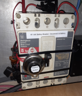
There is no arch with a resistor, you push the bypass button on and the resistor slowly charges the capacitors so there is no spark. In my case there is a 20 amp fuse on the right bypassing the ground and a 50 ohm resistor on the left connected to a resistor. Just push bypass button till the inverter lights up, then flip the breaker on, Joe.


MrM1
I'm Here, But I'm Not All There
@Joe BoyKey once you turn the breaker on, does that disengage the resistor? Or does the resistor just stay on?
Joe BoyKey
Watts, Watts, more Watts
Once breaker is on just let off the button to disengage the resistor.
MrM1
I'm Here, But I'm Not All There
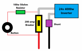
@Joe BoyKey Really like the design, it would be the simplest to integrate into my design. Little confused on you saying "20 amp fuse on the right bypassing the ground". My ground goes direct to the inverter thru a shunt. But is this the basic idea? (see Diagram)
- Where do you get the Button, or what is it called?
- What would be the load rating for the button?
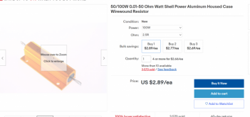
- Would a 50 ohm 100w resistor be OK ? Too big, too small?
- What gauge wire would be acceptable for the button/resistor?

- Where do you get the Button, or what is it called?
- What would be the load rating for the button?
- Would a 50 ohm 100w resistor be OK ? Too big, too small?
- What gauge wire would be acceptable for the button/resistor?

Joe BoyKey
Watts, Watts, more Watts
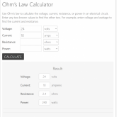
You won't need to bypass ground in your setup, just google 10amp Momentary push button, Ohm's law calculates 24v @ say 10 amps would be a 2.4 ohm resistor, not really critical thow. https://www.inchcalculator.com/ohms-law-calculator/ I have 48v @ 500ah.


MrM1
I'm Here, But I'm Not All There
@Joe BoyKey ... hey , Raj174 (over on the Wind and Sun Forum) says you might have a video of that button set up?
Joe BoyKey
Watts, Watts, more Watts
Similar threads
- Replies
- 85
- Views
- 4K
- Replies
- 10
- Views
- 488
- Replies
- 14
- Views
- 486
- Replies
- 3
- Views
- 331
- Replies
- 8
- Views
- 395


