diy solar

diy solar

Safety hazard w/ Growatt 5000ES (European version) when connected to American grid

there is no RCBO style safety devices on my country, i guess no one update the standards and we are working with old standards.
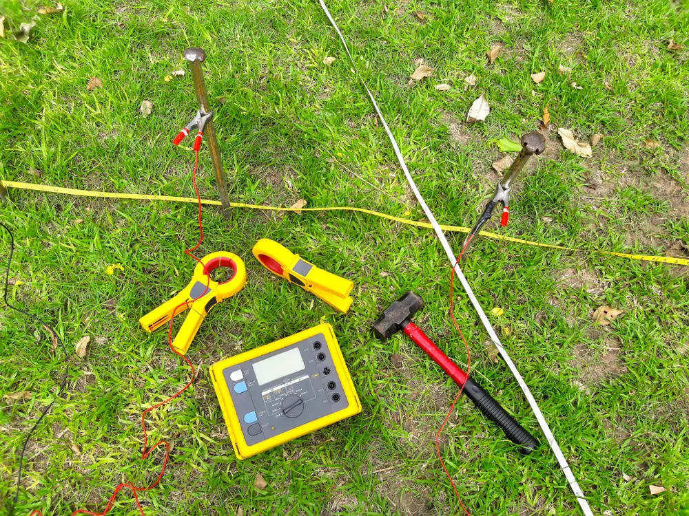
Again typically European standards for ground rod test impedances is < 1 ohm. ( I was present when we tested my mothers ground rod install recently )

Hence you circuit is “ safe “ as long as the ground loop impedance remains low. as a case fault will blow the fuses as needed.

However these days in the EU ground rod systems are largely defunct replaced by TT-C-S or TT-N-S, pure TT systems such as your diagram still exist.

EU codes now demand all house RCBO so new installs will have them.

Many older domestic installs are unsafe by modern wiring codes.

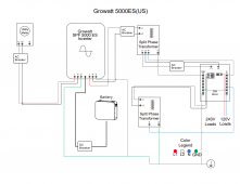
The overriding point is your diagram is not representative of a typical US split phase supply and grounding

However your diagram is not unsafe but it’s not up to modern expectations in AC safety , this requires adding extra protection. ( edited for clarity )

Hence your diagram merely adds confusion to the debate
 
Last edited:
"However your diagram is not unsafe but it’s not up to modern expectations is safety this requires adding extra protection."

Nice to hear this, thanks.
 
No. I’m a professional EE. Hence I can feel competent to review the technical argument and make a conclusion

I do not have a PE license.


Rating agency approval and safety are of course not the same

Yes, I'm evaluating whether it is safe.
(but I pointed out that the particular auto-transformer was granted UL listing. The system with inverter and autotransformer as shown was not.)

Firstly you understand this is a European derived circuit.

In such cases a whole house RCBO is fitted

No. In this case this is a European derived circuit , there is no consumer panel neutral earth bond , only a earth rod.

Secondly there will be a whole house RCBO 30mA trip

This schematic was provided to show how to take a European model inverter, add an auto-transformer, and use in the U.S. market. Where there is not a whole house RCBO. It could have shown "GFIC breaker" feeding inverter to solve at least some issues but it did not.

If I'm not mistaken, this schematic (or another like it with no ground connection between utility meter and inverter) was posted by Signature Solar for their U.S. customers. I pointed out the same flaw then.

Firstly in Europe ground loop impedance must be around 0.8 ohms or it’s not acceptable

Hence the ground circuit will not be raised. By anything like you say , and the short circuit /over load breakers will be tripped

This link says 5 ohms or less (except for very large installations with larger grounding system.)


This one quotes 25 ohms for residential, which is the figure I gave.


I don't think your soil in Europe is more conductive.


this circuit illustrated by “ hedges “ is a European floating neutral example

Being used in the U.S.

In a US version the case ground of the invertor ( and not L2/ neutral ) would always be grounded in the normal fashion

Hence any live fault to case ground would trip the distribution panel breakers or the output overload protection breakers.

25 ohms, and possibly 5 ohms, would not trip breaker. (But residual current breaker it would trip.)

U.S. code requires all systems in the building bonded together.
The schematic did not bond ground of utility meter to inverter, so is not compliant.

Hence it would be completely safe

Except the circuit breaker didn't trip, so it is not safe.

I'm not a licensed PE, but I showed how the circuit as shown would electrify "ground" of the system.
An isolation transformer could be used to make it safe (with proper grounding, and bonding of neutral to ground.)


If used with residual breaker, that would disconnect it. Without that, it is not safe. Even if "floating", which it won't be if a neighbor also has a fault of the other phase to ground.

If you see earthworms wriggling to the surface, be careful about "step potential".
 
I see a problem, a safety hazard. The Devil is in the details.

Is there a schematic showing how to connect grid and transformer?
"Line" input to "Line1" from grid, "Neutral" input to "Line2" from grid?

Manual says,
"...and a UPS function module in one machine, which is perfect for off grid backup power and self-consumption applications."
"Solar and utility grid can power loads at the same time"

I think this means it can pass grid AC input to loads through a relay, and when grid is down opens the relay (likely SPST isolating line only, not neutral), then drives 240Vrms AC on output Line relative to Neutral (which designers thought was ground.)

With output Line and Neutral connected to an auto-transformer having center tap grounded, Line is 120Vrms and "Neutral" is driven to 120Vrms (180 degrees out of phase for 240V total).

If only Line not Neutral is isolated by relay, so utility Line1 isolated but Line2 not, this would drive 120Vrms back into Line2.
It would not be apparent when tested by disconnecting both Line1 and Line2 with a 2-pole breaker. But during a power failure, there would be serious problems.

Yes you are spot on. Results in possible fire.
 
In mi case fire is not a problem, no wood house (concrete) and the inverter have his own room away from my house.
Funny you say that. I too have seperate room. I also live in concrete house. I was totally surprised when lost grid power. Promptly went out to turn on inverter. Well that was near impossible,turning off grid breaker and using transfer switch to inverter turn on breaker to power load from inverter. Make sure transformer breaker in load panel is on,always is.
Well it was off ,hmmm I say. Flip on breaker it flips off ,try again it stays. Horray I say. Walk in house dam there is a fire in the large ceramic pot I use to put Kolbenz surge protector voltage protection cord with phone charges etc. . Dam put it out. Kolbenz surge protector melted., but hay we have lights. I then have electrician come check circuits. We found another plug outlet fried black.
Called SS they said would replace. Ok, I say that takes 2.5 months. Not all SS fault. Shipping crisis, etc.
Ss did after 6 weeks of waiting for stock send new unit.
Install it and next morning error code.
I promptly disconnected from grid and wired my inverter ac out to transformer per instructions on transformer, then to transfer switch,to load panel.
I am thankful Timeselectric was helpful in guiding me and critiquing my drawings. I now have safe and very good results.
Just saying it maybe unlikely event, but it does happen.
SS has been good about sending new product. Thankful for that.
Oh and thank God for surge protectors. I lost 4 in all that night. Appliances were all saved.
 
People here are making all sorts of spurious claims

Heres the reccomendation. Li

What is a good ground
resistance value?
There is a good deal of confusion as to what constitutes a good ground and what the ground resistance value needs to be. Ideally a ground should be of zero ohms resistance.
There is not one standard ground resistance threshold that is recognized by all agencies. However, the NFPA and IEEE have recom- mended a ground resistance value of 5.0 ohms or less.
The NEC has stated to “Make sure that system impedance to ground is less than 25 ohms specified in NEC 250.56. In facilities with sensi- tive equipment it should be 5.0 ohms or less.”
The Telecommunications industry has often used 5.0 ohms or less as their value for grounding and bonding.
The goal in ground resistance is to achieve the lowest ground resistance value possible that makes sense economically and physically.

For example the legal limit in the U.K. is 5 ohms AND a mandatory RCD must be fitted in a TT only system.
 
again folks. In the US with incoming neutral earth bonded , thd European invertor running on US 240 vac , ie L1 and L2 mist never have a “ neutral earth bond and thus is a L2 earth bond “

The case is connected to PE S in all cases.

An auto transformer being used to recreate split phase is fine and safe once used within specifications

The neutral on this auto is bonded to PE

For additional “ belt and braces safety “ 30 mA RCBO devices can be fitted to the invertor input and output. It’s a cheap additional form of protection

There’s nothing really else to say here
 
Funny you say that. I too have seperate room. I also live in concrete house. I was totally surprised when lost grid power. Promptly went out to turn on inverter. Well that was near impossible,turning off grid breaker and using transfer switch to inverter turn on breaker to power load from inverter. Make sure transformer breaker in load panel is on,always is.
Well it was off ,hmmm I say. Flip on breaker it flips off ,try again it stays. Horray I say. Walk in house dam there is a fire in the large ceramic pot I use to put Kolbenz surge protector voltage protection cord with phone charges etc. . Dam put it out. Kolbenz surge protector melted., but hay we have lights. I then have electrician come check circuits. We found another plug outlet fried black.

Do you have a wiring diagram?

My assumption is 240V on the 120V circuits.
Called SS they said would replace. Ok, I say that takes 2.5 months. Not all SS fault. Shipping crisis, etc.
Ss did after 6 weeks of waiting for stock send new unit.
Install it and next morning error code.
I promptly disconnected from grid and wired my inverter ac out to transformer per instructions on transformer, then to transfer switch,to load panel.
I am thankful Timeselectric was helpful in guiding me and critiquing my drawings. I now have safe and very good results.
Just saying it maybe unlikely event, but it does happen.
SS has been good about sending new product. Thankful for that.
Oh and thank God for surge protectors. I lost 4 in all that night. Appliances were all saved.
 
Check one of Ian watts247 videos, it shows what happens perfectly. 120v bulb across each "phase"
Remove "neutral" and bulbs stay lit totally normal. Now add an extra load to one "phase" like a toaster and the bulb on the other side will flare up and blow.
Basically you just added a wire to the 120 volt bulb connecting it across 240 volts. It's going to have a bad day now.
 
  • Like
Reactions: Rho
Check one of Ian watts247 videos, it shows what happens perfectly. 120v bulb across each "phase"
Remove "neutral" and bulbs stay lit totally normal. Now add an extra load to one "phase" like a toaster and the bulb on the other side will flare up and blow.
Basically you just added a wire to the 120 volt bulb connecting it across 240 volts. It's going to have a bad day now.
In my diagram this scenery can't happen.
 
Check one of Ian watts247 videos, it shows what happens perfectly. 120v bulb across each "phase"
Remove "neutral" and bulbs stay lit totally normal. Now add an extra load to one "phase" like a toaster and the bulb on the other side will flare up and blow.
Basically you just added a wire to the 120 volt bulb connecting it across 240 volts. It's going to have a bad day now.
Yes this is the issue with floating neutral in a split phase system. It’s why neutral is grounded in split phase On the output of the auto transformer ( as it is in this circuit )
 
Nothing to do with that at all.
Ground/earth depending where you are in the world is for human safety, nothing to do with "light bulb" safety.
Half way down this page
why are ac circuits grounded
If you generate split phase from a relatively low power auto transformer and you unequally load the phases you will drag the neutral towards the higher loaded phase , this then create a higher voltage phase on the other split resulting in potegyoxk damage.

Referencing the neutral to earth ground “ anchors “ the neutral in this case the overloaded phase is pulled down but the other phase holds basically the same voltage as before.

There is a very serious deficit in this thread of first principle understanding and far too much obscure references to only slightly understood custom and practice techniques.
 
No kidding, you are a prime example of this practice.
Given I have explained in precise detail and I have 35 years experience in the field as a professional I don’t regard your BS remark as useful to people.

There are clearly people here who do not understand the fundementals behind mains earth grounding and are mixing up things , betraying their lack of understanding.

That’s fine , but it’s not the truth.

In my case I have laid out the safe path to using a European 240 on a US split phase system.
 
Last edited:
In my case I have laid out the safe path to using a European 240 on a US split phase system.

Do you tie ground of the inverter, transformer, breaker panel, and loads to ground of the utility meter and main breaker panel at service entrance?
 
Back
Top