


You are using an out of date browser. It may not display this or other websites correctly.
You should upgrade or use an alternative browser.
You should upgrade or use an alternative browser.
Safety hazard w/ Growatt 5000ES (European version) when connected to American grid
- Thread starter Will Prowse
- Start date
Goboatingnow
Solar Enthusiast
- Joined
- Jul 3, 2022
- Messages
- 1,325
But it’s not. There’s no specific electrical requirement for that to be the case. The grounding can happily be established at the auto transformerThat does not address the fact that the input is designed for one leg to be at or near ground potential.
Basic Engineering 101
The inverter INPUT is designed for one leg to be at or near ground potential.
Using a Euro inverter on a split phase grid puts 125 vac on the input designed for at or near ground potential
The autotransformer only deals with the OUTPUT of the inverter
The ONLY safe way to use a EURO inverter on a split phase grid would to use a full isolation transformer on the input as well as using the full isolation transformer on the output which is wired 230 volts in and 120/240 volts out
AND the neutral path must be continuous.........I.E. split phase neutral from utility connected to the INPUT full isolation transformer OUTPUT (neutral) terminal and then connected to output full isolation transformer neutral terminal
But then again do what you want, I legally cannot suggest do what you are trying to do
I do not need the liability
Goboatingnow
Solar Enthusiast
- Joined
- Jul 3, 2022
- Messages
- 1,325
The inverter INPUT is designed for one leg to be at or near ground potential.
No it’s not. The invertor does not care where the L1 and L2 are referenced . ( in fact many euro mains are not ground neutral ground referenced at all. ) in this scenario. Break any neutral ground connection as it shouldn’t be there.
No the input is 240VAC ie the potential differenceUsing a Euro inverter on a split phase grid puts 125 vac on the input designed for at or near ground potential
The autotransformer only deals with the OUTPUT of the inverter
Correct this shoujd only be used in invert mode only.
The ONLY safe way to use a EURO inverter on a split phase grid would to use a full isolation transformer on the input as well as using the full isolation transformer on the output which is wired 230 volts in and 120/240 volts out
Sorry there’s no justification electrically for that.
If you use a 240 VAC single phase invertor do not connect it to ground , The output is floating.AND the neutral path must be continuous.........I.E. split phase neutral from utility connected to the INPUT full isolation transformer OUTPUT (neutral) terminal and then connected to output full isolation transformer neutral terminal
But then again do what you want, I legally cannot suggest do what you are trying to do
I do not need the liability
To get split phase then use an auto transformer and in invert or grid tied mode connect the centre tap ( ie neutral ) to the system ground
The key is to regard the invertor as a “ component “ and not a generator output.
The problem only occurs if you inadvertently ground the invertor and reference it’s output to ground. This is wrong if the split phase output is then also grounded.
It’s simple if you are going down this route regard the “ auto transformer “ as the invertor output and ground as normal.
Last edited:
Goboatingnow
Solar Enthusiast
- Joined
- Jul 3, 2022
- Messages
- 1,325
In a euro invertor , no that assumption is false as several countries floating L1 and L2 rather like the US split phase. In euro land you never assume the neutral is at ground potential ( Italy is TT for example )That does not address the fact that the input is designed for one leg to be at or near ground potential.
Basic Engineering 101
In many cases homes are fed with three phase directly so again all TT basis
( Norway is for example fed as per US split phase approach, two live conductors to get 230 )
Americans tend to sssume Europe is electrically like the U.K. this is absolutely not the case.
As I says the provision of auto bonding neutral ground relays is controversial in Europe, Many regulators feel this should be done externally.
Last edited:
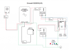
This is how I connect my components.
We use USA system (120v/240v split phase) in my country but there is no ground bar on the utility meter (so there is no bonding neutral-ground) on any house in my country, most Plugs are 2 legs on all houses.
We use USA system (120v/240v split phase) in my country but there is no ground bar on the utility meter (so there is no bonding neutral-ground) on any house in my country, most Plugs are 2 legs on all houses.
Attachments
Last edited:
Hedges
I See Electromagnetic Fields!
- Joined
- Mar 28, 2020
- Messages
- 20,853
Auto transformer will establish a midpoint between two wires 240V apart.
If the 240V single-phase inverter has two connections "L" and "N", does the "N" comply with creepage and clearance requirements to be operated 120V above ground? The inverter should be designed and tested for that.
It does appear that with proper switching an auto transformer can let a 240V isolated inverter interact with the 120/240V split-phase utility grid and also supply split phase when grid is disconnected. Victron has a product for that.
Some of the schematics I've seen, when connected to grid, if a fault occurs between line and chassis the breakers will not clear it and chassis remains hot.
You have to determine not only that the system will function properly when everything is good, but also that it will remain safe when any faults occur.
In your drawing: https://diysolarforum.com/attachments/5000es-us-with-breakers-autotransformer-png.118315/
You are missing a ground connection back to the utility meter.
If a fault develops between incoming L1 or L2 to inverter chassis, your entire ground network is now at 120V.
Some current will flow through the earth due to your ground rod off the breaker panel, but not enough to trip "AC breaker" at utility meter.
Touching your equipment and anything (e.g. water pipe) with other ground connection will result in a shock.
If the 240V single-phase inverter has two connections "L" and "N", does the "N" comply with creepage and clearance requirements to be operated 120V above ground? The inverter should be designed and tested for that.
It does appear that with proper switching an auto transformer can let a 240V isolated inverter interact with the 120/240V split-phase utility grid and also supply split phase when grid is disconnected. Victron has a product for that.
Some of the schematics I've seen, when connected to grid, if a fault occurs between line and chassis the breakers will not clear it and chassis remains hot.
You have to determine not only that the system will function properly when everything is good, but also that it will remain safe when any faults occur.
This is how I connect my components.
We use USA system (120v/240v split phase) in my country but there is no ground bar on the utility meter (so there is no bonding neutral-ground) on any house in my country, most Plugs are 2 legs on all houses.
In your drawing: https://diysolarforum.com/attachments/5000es-us-with-breakers-autotransformer-png.118315/
You are missing a ground connection back to the utility meter.
If a fault develops between incoming L1 or L2 to inverter chassis, your entire ground network is now at 120V.
Some current will flow through the earth due to your ground rod off the breaker panel, but not enough to trip "AC breaker" at utility meter.
Touching your equipment and anything (e.g. water pipe) with other ground connection will result in a shock.
I have 2 supervisors with a contactor that check L1 L2 and N faults.Auto transformer will establish a midpoint between two wires 240V apart.
If the 240V single-phase inverter has two connections "L" and "N", does the "N" comply with creepage and clearance requirements to be operated 120V above ground? The inverter should be designed and tested for that.
It does appear that with proper switching an auto transformer can let a 240V isolated inverter interact with the 120/240V split-phase utility grid and also supply split phase when grid is disconnected. Victron has a product for that.
Some of the schematics I've seen, when connected to grid, if a fault occurs between line and chassis the breakers will not clear it and chassis remains hot.
You have to determine not only that the system will function properly when everything is good, but also that it will remain safe when any faults occur.
In your drawing: https://diysolarforum.com/attachments/5000es-us-with-breakers-autotransformer-png.118315/
You are missing a ground connection back to the utility meter.
If a fault develops between incoming L1 or L2 to inverter chassis, your entire ground network is now at 120V.
Some current will flow through the earth due to your ground rod off the breaker panel, but not enough to trip "AC breaker" at utility meter.
Touching your equipment and anything (e.g. water pipe) with other ground connection will result in a shock.
I cant connect the ground on the meter because others house don't have it, if a fault on N on my street occur all N of the street are going to try to use my ground. Like i say i don't know why in my country there is no ground on the meter, but it work like that since we have electricity here...

Last edited:
Hedges
I See Electromagnetic Fields!
- Joined
- Mar 28, 2020
- Messages
- 20,853
I have 2 supervisors with a contactor that check L1 L2 and N faults.
Residual current detector, disconnects if ground leakage occurs?
That may do what is needed in your situation.
For people in the U.S. using these European models, neutral at the meter is grounded and they don't have that RCD (GFIC) breaker, so it is a problem.
Maybe if U.S. customers fed the inverter through a 2-pole GFIC it would solve that particular issue.
They may yet experience some voltage offset of their grounded center tap, so some current flowing through the earth (earthworms franticly wriggle to the surface.) You could see the same if a neighbor also uses an auto transformer.
Goboatingnow
Solar Enthusiast
- Joined
- Jul 3, 2022
- Messages
- 1,325
This cannot be correct as you as creating the same problem as the US system. and you have a complete floating neutralThis is how I connect my components.
We use USA system (120v/240v split phase) in my country but there is no ground bar on the utility meter (so there is no bonding neutral-ground) on any house in my country, most Plugs are 2 legs on all houses.
Goboatingnow
Solar Enthusiast
- Joined
- Jul 3, 2022
- Messages
- 1,325
No it disconnects if the lve feed and neutral return currents differResidual current detector, disconnects if ground leakage occurs?
That may do what is needed in your situation.
For people in the U.S. using these European models, neutral at the meter is grounded and they don't have that RCD (GFIC) breaker, so it is a problem.
No it’s not.
No need just leave the invertor float establish neutral bonding at the AutoMaybe if U.S. customers fed the inverter through a 2-pole GFIC it would solve that particular issue.
They may yet experience some voltage offset of their grounded center tap, so some current flowing through the earth (earthworms franticly wriggle to the surface.) You could see the same if a neighbor also uses an auto transformer.
Goboatingnow
Solar Enthusiast
- Joined
- Jul 3, 2022
- Messages
- 1,325
Auto transformer will establish a midpoint between two wires 240V apart.
If the 240V single-phase inverter has two connections "L" and "N", does the "N" comply with creepage and clearance requirements to be operated 120V above ground? The inverter should be designed and tested for that.
Yes it does it must. EU regs do not assume neutral is any difference to live.
There is no issue as long as you do not neutral bond at the invertorIt does appear that with proper switching an auto transformer can let a 240V isolated inverter interact with the 120/240V split-phase utility grid and also supply split phase when grid is disconnected. Victron has a product for that.
Some of the schematics I've seen, when connected to grid, if a fault occurs between line and chassis the breakers will not clear it and chassis remains hot.
No. Chassis is never connected to neutral. It’s connected to ground.You have to determine not only that the system will function properly when everything is good, but also that it will remain safe when any faults occur.
All my country is a big floating neutral and it work, not sure why the engineer here do this, i know the correct way is ground all the houses on the meter and bound it to neutral but what i can do? i have to put working my system and always use good protection and pray to god (lol) when working with the inverter.This cannot be correct as you as creating the same problem as the US system. and you have a complete floating neutral
Goboatingnow
Solar Enthusiast
- Joined
- Jul 3, 2022
- Messages
- 1,325
Fundementslky here is the misunderstanding of the role of ground and its relationship to neutral
Goboatingnow
Solar Enthusiast
- Joined
- Jul 3, 2022
- Messages
- 1,325
Yes sorry , i agree as I said many European countries have fully floating neutralsAll my country is a big floating neutral and it work, not sure why the engineer here do this, i know the correct way is ground all the houses on the meter and bound it to neutral but what i can do? i have to put working my system and always use good protection and pray to god (lol) when working with the inverter.
Hedges
I See Electromagnetic Fields!
- Joined
- Mar 28, 2020
- Messages
- 20,853
No it disconnects if the lve feed and neutral return currents differ
Correct, it actually measures difference between line and neutral. What I meant was, if ground leakage occurs (like a person getting a shock between line and ground), that results in a few milliamps difference between line and neutral so GFCI detects that and disconnects.
No it’s not.
No need just leave the invertor float establish neutral bonding at the Auto
If people in the US use a European 240V inverter and an auto transformer, several issues occur.
If their inverter and auto-transformer were just used as a "generator" through a transfer switch, no problem. But feeding grid through the inverter, there are several issues. The Victron design appears correct to me.
No. Chassis is never connected to neutral. It’s connected to ground.
Chassis of inverter is bonded to ground.
Chassis of utility meter and disconnect switch is boded to ground.
At least in the U.S., neutral of utility is bonded to ground at about the first disconnect.
In the drawing Pendrak provided, neutral was bonded to ground at the breaker panel. Neutral from breaker panel wired to neutral of the transformers and loads. Ground wired to breaker panel, autotransformer, inverter, loads.
The so-called "neutral" of the inverter did not wire to ground because it was really "line". (in the case of a split-phase inverter, its neutral would bond to ground somewhere. In my case that is at utility entrance.
Pendrak's drawing showed a neutral at the utility meter, not connected to anything. (Don't know for sure but think it is a center tap of utility transformer, but not grounded in his country he said?) For anyone in the U.S. using that schematic, I've got problems with it, starting with "ground" not connected between utility meter and inverter. Correct that and I'll probably find another problem.
What I said was,
"You have to determine not only that the system will function properly when everything is good, but also that it will remain safe when any faults occur."
Do you disagree?
Quattrohead
Solar Wizard
It is a terrible hack and completely stupid and potentially extraordinarily dangerous on so many fronts. Yes of course you'll produce your split phase 120 volts and your American light bulb will light up and you can put your cheesy grin on YouTube and exclaim hey it works but it is a fucking stupid thing to do.While an auto transformer is a bit of a hack true. It’s perfectly safe and usable
Goboatingnow
Solar Enthusiast
- Joined
- Jul 3, 2022
- Messages
- 1,325
It doesn’t have to be a ground fault currentCorrect, it actually measures difference between line and neutral. What I meant was, if ground leakage occurs (like a person getting a shock between line and ground), that results in a few milliamps difference between line and neutral so GFCI detects that and disconnects.
The key using a auto transformer is to regard the inverter feeding it as a “ component “. Hence there should be NO earth neutral bond established there in the 240 vac inverter because what you are doing is bonding a live to earth.If people in the US use a European 240V inverter and an auto transformer, several issues occur.
If their inverter and auto-transformer were just used as a "generator" through a transfer switch, no problem. But feeding grid through the inverter, there are several issues. The Victron design appears correct to me.
Victron do the same thing
The bonding of the chassis to ground is irrelevant , it’s the bonding of neutral to ground at the inverter is wrongChassis of inverter is bonded to ground.
Chassis of utility meter and disconnect switch is boded to ground.
Yes that’s not the issue hereAt least in the U.S., neutral of utility is bonded to ground at about the first disconnect.
That drawing is fine , as there should be no bonding in the inverter between neutral and ground.In the drawing Pendrak provided, neutral was bonded to ground at the breaker panel. Neutral from breaker panel wired to neutral of the transformers and loads. Ground wired to breaker panel, autotransformer, inverter, loads.
The key point is Neutral PE cannot bond at the inverter and the centre tapnof the suto transformer
There can only be one neutral PE bond per system.
Yes in the 240vac European inverter in a US split phase system , the key point is the neutral cannot be bonded as it’s actually L2The so-called "neutral" of the inverter did not wire to ground because it was really "line". (in the case of a split-phase inverter, its neutral would bond to ground somewhere. In my case that is at utility entrance.
In his country , as I mentioned neutral is floating. Many European countries have floating neutrals, ie in effect it can be regarded as L2. It’s no difference from US split phasePendrak's drawing showed a neutral at the utility meter, not connected to anything. (Don't know for sure but think it is a center tap of utility transformer, but not grounded in his country he said?) For anyone in the U.S. using that schematic, I've got problems with it, starting with "ground" not connected between utility meter and inverter. Correct that and I'll probably find another problem.
That diagram is fine for the US , as long as the inverter does not bond L2 ( ie a floating neutral ) to earth.
What I said was
Yes but clearly people here seem to think neutral is the same as earth. Neutral is a “ live wire “"You have to determine not only that the system will function properly when everything is good, but also that it will remain safe when any faults occur."
Do you disagree?
Goboatingnow
Solar Enthusiast
- Joined
- Jul 3, 2022
- Messages
- 1,325
There is nothing unsafe. The issue here is people assuming European neutral is not a live wire and therefore can be automatically bonded to earthIt is a terrible hack and completely stupid and potentially extraordinarily dangerous on so many fronts. Yes of course you'll produce your split phase 120 volts and your American light bulb will light up and you can put your cheesy grin on YouTube and exclaim hey it works but it is a fucking stupid thing to do.
A European 240 invertor produces a waveform identical to US split phase 240 , ie L1 and L2 , assuming frequency is the same. , since L2 on US split phase IS NOT neutral or earth bonded , then why would you bond the European L2 to earth. This output is essentially a split phase. This is the key confusion here and the error people are making
The auto transformer regenerates a neutral from the then 240 “ split phase “ from the 240 invertor
Then you can now ground reference that neutral from the Auto transformer , by bonding , essentially recreating the US split phase . By bonding it to earth
This is no different to a US split phase invertor , just regard the 240 inverter and auto transformer as one complete unit.
Hence the takeaway is simple , if you are using a European inverter to generate US240vac , dont assume you have a live and neutral output , you don’t , you have two live outputs , do not bond a live output to earth,
( an RCD in the output will add protection from inadvertent shock paths but isn’t needed per say.)
Last edited:
Quattrohead
Solar Wizard
I am not qualified or smart enough to justify all of this hack work, I just read what far more intelligent and knowledgeable people than us have written on here in the past and take their advice to heart.
But the more that people try to argue this is a perfectly fine situation the more I realize it actually is not and I wonder what some people's motives are.
Ac voltage is a weird and wonderful thing that can really hurt us if we disrespect it, just like DC voltage.
I feel very fortunate to be able to learn from far clever people than me on here.
I worked for Kodak in main labs on three phase 400 volt machines with highly conductive liquids and I respected the living daylights out of that shit because one wrong move and I was very dead.
Similar threads
- Replies
- 6
- Views
- 280
- Replies
- 1
- Views
- 209
- Replies
- 5
- Views
- 442
- Replies
- 3
- Views
- 336