diy solar

diy solar

Schneider xw pro 6848 not powering up with eg4 lithium battery

Point taken.
But, the key is "pre" charge.

1. Power on battery. (In theory precharge happens here, but in this case there's no capacitors connected to have any in-rush current)
2. Precharge Inverter with external resistor.
3. Close inverter DC breaker.
I think based on what is happening with LifePower I think it's more like this.

1) Power on BMS
2) Switch on the external Breaker which then starts the PreCharge Process when a load is detected.
3) It waits for the voltage to reaches past a certain Voltage level and time interval.
4) It then energize the Mofets on the BMS when #3 is complete.

I think the problem with the EG4 Lifepower is that it cannot reach the voltage level before the time Interval so the Mosfets never get energized and the Inverter just clicks away trying to start with whatever power has been put in its capacitors.

Second and more likely possibility is that the charge resistor never disengages after the time interval is up because the voltage is too low and then the BMS is locked out of powering the Mosfets due to a possible overload.
So the Inverter is trying to start with insufficient current as the 20 Ohm resistor limits its consumption to about 2.5 Amps. This would be some kind of bug in the BMS firmware or hardware design that is preventing it from just resetting and trying the process again.

An external Jump start may be why it can get past the problem. Once the Voltage goes past the threshold it is seems like the BMS is unlocked and can engage the Mosfets.

The EG4LL has a Timer that can be changed in the software. I have seen it in the options menu.
It apparent that the voltage level is reached before the time interval expires so that is why it powers up the Inverter without a problem. If it is not reaching the level it would imply that it does not have that same bug so it just restarts the Pre-Charge sequence again.

If I had @Koldsimer Inverter and both batteries I could hook them up one at a time to an Oscilloscope and see exactly what is happening.
 
In order for pre-charge to start, the BMS must first trip off from surge overload current.

This defeats the primary purpose of preventing high surge current (>1000 amps) from pitting breaker contacts.

BMS's do not normally have fast switching speed. It is possible but requires high current MOSFET gate drivers to shut down the massive amount of multiple parallel low Rd_ON MOSFETs' gate capacitance.
 
Last edited:
Just so everyone knows, I'm still here to discuss. The other thread we started is simply us trying to get everyone who is still having issues the ability to contact us and get help. You are also welcome to keep PMing me if you would like as well.
 
Ok, I’m back off vacation so can join back in the conversation. Well as you know first of all it won’t even start the system up so doesn’t much matter what I am running, but here are a couple items that kill it when I get the battery running (it is 1 single rack system as previously shown 400ah). 1500w microwave, 13500 btu Coleman Mach Airconditioner. Now keep in mind I just spent a week out of town and the system worked flawless using another brand battery with built in BMS. Even ran the AC unit for around an hour while stopped at a rest stop While watching tv and eating lunch. I have not checked the starting amperage on the ac unit but can climb up on the roof and remove the shroud to check. At this point I really don’t want to waste my time or effort unless you are planning on taking the battery back. If you would like me to conduct some tests so as to assist you before you take it back I would be happy to, but if all of this is just to tell me it should work and must be something in my system I have better things to do. Just didn’t want to get stuck with an expensive paper weight. Attached is yesterdays usage on a very overcast day, not sure if that will help you in anyway.
PM me directly.
 
In order for pre-charge to start, the BMS must first trip off from surge overload current.
I don't think the BMS can engage the Mosfets until it detects a certain voltage level across the terminals.
If the Pre-Charge fails to get a high enough voltage established then it won't let the Mosfets gates get powered.

This defeats the primary purpose of preventing high surge current (>1000 amps) from pitting breaker contacts.

BMS's do not normally have fast switching speed. It is possible but requires high current MOSFET gate drivers to shut down the massive amount of multiple parallel low Rd_ON MOSFETs' gate capacitance.
I think in the case of the Lifepower it does not even get a chance to switch on the Mosfets.
 
Last edited:
Possible work-around for built-in precharge that doesn't handle a particular load ...
Connect a capacitor outside the battery, turn on battery to let it precharge and turn on its MOSFETs. (Do they stay on after that?)
Then use your own external precharge resistor and switch to power up your inverter, as if battery didn't have one built in.

(I think somebody else proposed this earlier).

If you have separate SCC and inverter, SCC capacitors might do the trick. Wire SCC before the big inverter switch (which has precharge circuit around it), wire inverter after big switch.
 
Possible work-around for built-in precharge that doesn't handle a particular load ...
Connect a capacitor outside the battery, turn on battery to let it precharge and turn on its MOSFETs. (Do they stay on after that?)
Then use your own external precharge resistor and switch to power up your inverter, as if battery didn't have one built in.

(I think somebody else proposed this earlier).
Yes I proposed it and another EE also proposed the idea later on but we were both ignored.
If you have separate SCC and inverter, SCC capacitors might do the trick. Wire SCC before the big inverter switch (which has precharge circuit around it), wire inverter after big switch.
 
Wow... I made it through all 46 pages, and am still left with a few questions if anyone will indulge me. (I am trying to decide on equipment for my place.)
  • @Koldsimer - Out of curiosity, what is the temperature and humidity under your house? Is it fully insulated and vapor barriered, or just indirectly warmed from the floor above with no measures to control moisture migration?
  • @RichardfromSignatureSolar - Signature Solar might do well to invest in logging volt/current meters to send to customers having issues. It killed me that there was no detailed log of time/current initially on the DC output, and subsequently a voltage log across the pre-charge resistor.
 
Yes, it is VERY hard (or impossible) to debug a problem without sufficient data.

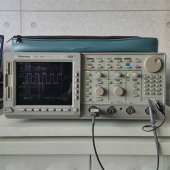
In this particular and VERY long thread, (46 pages as of now), I have a strong feeling that this could have been figured out by using an oscilloscope reading the battery voltage as the Schneider inverter tried to turn on. Just a second or two of scope capture.

Do any of the parties involved here have an oscilloscope ? A voltmeter is just not going to cut it for this problem as the voltage dips are most likely too short to see.

The proper tool for the job.
boB
 
Do any of the parties involved here have an oscilloscope ? A voltmeter is just not going to cut it for this problem as the voltage dips are most likely too short to see.

The proper tool for the job.
boB
A scope is great, but you can get by with any number of lower cost loggers. They can do up to 4-5,000 samples per second. You would see pretty much even with just 20 samples per second... enough to confirm how different units are actually operating.
 
A scope is great, but you can get by with any number of lower cost loggers. They can do up to 4-5,000 samples per second. You would see pretty much even with just 20 samples per second... enough to confirm how different units are actually operating.

Sure, a fast logger would be just as good in this case and would show the same thing.

Do you have any particular ones in mind ? I would not mind having one myself.

There are also low cost portable scopes but they are usually not very good as an oscilloscope.
 
I think the one we use at work is like this:


Voltage & current probes, FFT to see harmonics.


Oh, you said, "low cost" :)

Here's what I use at home. The last one I bought cost about $400

1649480076809.png

And this is my logger (DAS).
I can pre-program it, plug in to gather data standalone.
But need PC to view graphs, and easiest to program that way as well.

1649480188388.png
 
Do you have any particular ones in mind ? I would not mind having one myself.
AEMC made some reasonably cheap ones a few years back, not sure about their current offerings. Voltage logging is more of a commodity than DC current monitoring, but it shouldn't be too hard without going the shunt route.
 
Yes, for this issue, voltage is probably enough to verify what is happening. I mean, you could certainly infer there is high current causing the drop in voltage if that is what is happening. And WHEN it is happening. Is it only when charging the capacitors or is it when the inverter turns on or ?
 
I think the one we use at work is like this:


Voltage & current probes, FFT to see harmonics.


Oh, you said, "low cost" :)

Here's what I use at home. The last one I bought cost about $400

View attachment 90486

And this is my logger (DAS).
I can pre-program it, plug in to gather data standalone.
But need PC to view graphs, and easiest to program that way as well.

View attachment 90487

THAT $400 scope is great but isn't the "low cost" I was talking about. I meant one of those handheld 2 channel scopes that cost like, $75 or something like that. They would log fine but are awful to work with in my experience. I am really glad you can get a decent digital scope now for that $400.

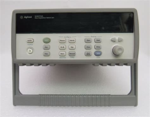
Isn't that Agilent logger the one with the array of relays in the plug-in module ? We have 3 of those at MidNite. For a few seconds I suppose it "might" work but those relays would be clicking away to beat the band !

I have never tried to run on at a fast rate. Fast meaning maybe every few seconds. We use those for temperature and voltage data logging over a couple or few hours time. They work great !
 
Wow... I made it through all 46 pages, and am still left with a few questions if anyone will indulge me. (I am trying to decide on equipment for my place.)
  • @Koldsimer - Out of curiosity, what is the temperature and humidity under your house? Is it fully insulated and vapor barriered, or just indirectly warmed from the floor above with no measures to control moisture migration.

Hey shimmy. Congrats on reading the entire thread! Your gift is in the mail!

The space under my house is fully sealed from the outside elements by metal skirting. I have never seen under house temps go below high 30's in the winter- even with single digit temps for extended times. Summer temps rarely see anything higher than 90. As far as moisture, it hasn't been a problem once i got the runoff figured out. I've never put a hygrometer under there to get an actual % but it isn't damp or moldy so it hasn't been much of an issue. No vapor barrier on the ground and r-19 in the floors.
 
Look at Salae
It has been used by some "big" companies.
Needs a laptop, and suitably attenuating probes. With 0.1" pin headers, meant more for analog/digital at the board level, would need an adapter so you get 100x attenuation from probe tip to this device.


THAT $400 scope is great but isn't the "low cost" I was talking about. I meant one of those handheld 2 channel scopes that cost like, $75 or something like that. They would log fine but are awful to work with in my experience. I am really glad you can get a decent digital scope now for that $400.

Isn't that Agilent logger the one with the array of relays in the plug-in module ? We have 3 of those at MidNite. For a few seconds I suppose it "might" work but those relays would be clicking away to beat the band !

I have never tried to run on at a fast rate. Fast meaning maybe every few seconds. We use those for temperature and voltage data logging over a couple or few hours time. They work great !

It was a $25k scope when new.
2M deep memory, 4 G/sample, 8 bit but high-res mode gives 13 bits.
My first one cost $2k on eBay. Going direct to the source (local liquidation auction), got one for $400.

New DSO these days offer modest performance for modest price. Here's 50 MHz Rigol for under $400


Those DAS with relay can switch channels for 60 readings/second.
Logging DMM might be faster for a single channel.
Need perhaps 1kHz readings to see battery sag during cycles of AC, but the capacitor charge inrush would be much faster than an AC cycle (if no precharge resistor).
Only thing a low-speed digitizer could show is RC delay if a precharge resistor is used, and how long after power applied before inverter starts drawing current.

A scope showing voltage and current traces is what's needed.
A CT can show reasonable frequency and current like 60 Hz ripple on battery cable.
For inrush, need something that can register 1000's of amps and millisecond rise time. Hall effect sensors aren't cheap.
A battery shunt and voltage probe might be the way to go.
 
Yes, for this issue, voltage is probably enough to verify what is happening. I mean, you could certainly infer there is high current causing the drop in voltage if that is what is happening. And WHEN it is happening. Is it only when charging the capacitors or is it when the inverter turns on or ?
We are running this under oscilloscope, the problem we face to be clear is that a new XW pro in our shop with the exact batteries (we took them back from @Koldsimer) with the exact same schneider firmware runs just fine off of 2 5000w packs, so we can see that voltage reacts to this but the levels in our shop will not represent failure of the unit.

we are collaborating directly with Eric at Schneider about this now, trying to get a categorical assurance relative to their circuit that we are in the clear
 
What waveforms did you get? Precharge curve voltage on input of inverter? Time before inverter draws current? How much current it draws?

Variation in those curves could cause one system to work but another to fail. You would want some margin on timing, and voltage levels if inverter is drawing a modest current through your precharge resistor.

i.e. analog and continuum of results, not just pass/fail.
 
We are running this under oscilloscope, the problem we face to be clear is that a new XW pro in our shop with the exact batteries (we took them back from @Koldsimer) with the exact same schneider firmware runs just fine off of 2 5000w packs, so we can see that voltage reacts to this but the levels in our shop will not represent failure of the unit.

we are collaborating directly with Eric at Schneider about this now, trying to get a categorical assurance relative to their circuit that we are in the clear
That is why it is really important to at least have the user be able to log some information for you. I would be very curious what happens at the low end of the operating temperature range and if that was not part of the problem. If this whole thread is bad press for SS, at least something useful could have been learned from it.

Oh well, hindsight 20-20 and all that.
 
I hate to bring up old statements again.
But I think most of the users had other batteries that were used to start up these inverter and which these batteries did start up the inverters .
The point is that there is something that is causing start up issues either with the area ,batch of the batteries or some other factor.
 
...there is something that is causing start up issues either with the area ,batch of the batteries or some other factor.
Agree, but most failure modes are a combination of factors. If it can't be recreated reliably (or documented in a way that there is sufficient information) then it cannot be solved. The question is what commonalities did people with failures have; there has not been enough data provided to help determine that.
 
My guess is it’s built in and I’m screwed, I’ve actually given up on trying to figure it out. It’s simple it doesn’t work, now the question is what if anything SS is willing to do.
I can't keep track of this thread any longer. Did they change your battery or do anything for you?
 

diy solar

diy solar
Back
Top