


You are using an out of date browser. It may not display this or other websites correctly.
You should upgrade or use an alternative browser.
You should upgrade or use an alternative browser.
Seplos BMS and RS485 coms to PC
- Thread starter CV350
- Start date

Hello Folks,
i would like to ask you if somebody had problem with BMS after try to upgrade 2.8 firmware. I used my own usb to RS485 cable to upgrade firmware (normal communication with bms thru software worked well) but during uploading firmware the system shut down with error "get package capacity fail" . Now i am not able to connect with BMS again + when i turn on BMS then system just show logo without any button response and after 30s just turn off. Thanks for any advice
i would like to ask you if somebody had problem with BMS after try to upgrade 2.8 firmware. I used my own usb to RS485 cable to upgrade firmware (normal communication with bms thru software worked well) but during uploading firmware the system shut down with error "get package capacity fail" . Now i am not able to connect with BMS again + when i turn on BMS then system just show logo without any button response and after 30s just turn off. Thanks for any advice
houseofancients
Solar Wizard
contact seplos...Hello Folks,
i would like to ask you if somebody had problem with BMS after try to upgrade 2.8 firmware. I used my own usb to RS485 cable to upgrade firmware (normal communication with bms thru software worked well) but during uploading firmware the system shut down with error "get package capacity fail" . Now i am not able to connect with BMS again + when i turn on BMS then system just show logo without any button response and after 30s just turn off. Thanks for any advice
doesnt sound good
Yes, exact same thing happened to us. Worked fine for 2 BMS units. The third failed as you described. Please let me know if you find a solution! For now we swapped in a spare.Hello Folks,
i would like to ask you if somebody had problem with BMS after try to upgrade 2.8 firmware. I used my own usb to RS485 cable to upgrade firmware (normal communication with bms thru software worked well) but during uploading firmware the system shut down with error "get package capacity fail" . Now i am not able to connect with BMS again + when i turn on BMS then system just show logo without any button response and after 30s just turn off. Thanks for any advice
shavermcspud
Solar Enthusiast
- Joined
- Mar 12, 2020
- Messages
- 579
I have the firmware to fix this as i had exactly the same problemFound nothing, talked with seplos and i need to send wrong one to them and then i will see. Btw you have original USB to RJ45? or "homemade" ?
Attachments
wow, i will try it, thank you ... so then 30s window when BMS is ON , its enought to upload new firmware?I have the firmware to fix this as i had exactly the same problem
Last edited:
We used the white USB to RJ45 supplied by Seplos.Found nothing, talked with seplos and i need to send wrong one to them and then i will see. Btw you have original USB to RJ45? or "homemade" ?
hmm tried it and still gettingI have the firmware to fix this as i had exactly the same problem

shavermcspud
Solar Enthusiast
- Joined
- Mar 12, 2020
- Messages
- 579
hmm tried it and still getting
View attachment 118677
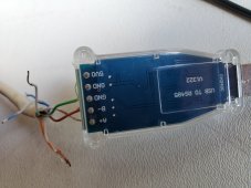
Then your cable doesnt have the ground, I had the exact same issue even though the same cable worked ok for reading the BMS data it failed on firmware flashing. procedure is load the flash utill and firmware, open the port and then turn on the BMS
I bought different adapter (old one could be damaged), made steps as you wrote and , ITS WORKS !!! Mr you are genius !Then your cable doesnt have the ground, I had the exact same issue even though the same cable worked ok for reading the BMS data it failed on firmware flashing. procedure is load the flash utill and firmware, open the port and then turn on the BMS
shavermcspud
Solar Enthusiast
- Joined
- Mar 12, 2020
- Messages
- 579
Most welcomeI bought different adapter (old one could be damaged), made steps as you wrote and , ITS WORKS !!! Mr you are genius !
Any one like this will work - https://amzn.eu/d/2fXmrzu they are all the same. You only need 3 wiresHijacking thread, can anyone recommend an adapter that is good / works?
Hi I'm in Italy, I have two 280Ah lifepo4 banks and two Seplos Can-Bus BMS in cascade on Sofar HYD6000-EP, if I set Master DIP-5-ON and Slave DIP-1-ON the inverter is OK it sees 560Ah but the PC doesn't connect anymore, if Master all DIP OFF and Slave DIP-1-ON the inverter sees 280Ah and the PC connects and I see the two BMS.Most welcome
Do you have a solution
Thanks
Hi Claudio
Translated with DeepL logo Translator
salut oui moi aussi j'ai des problem de cumunication oimpossible de communiquer sur 2 pcb v16 on dirai qui a des soudure mal faite du cotes des conecteur rj45 et sur le LA GRAVURE p+ A TU UN COMPOSANT OU PAS MERCI DE TA REPONSE A TU TROUVER UNE SOLUTION ,I am having problems getting the Seplos BMS to communicate with my PC via the standard RS485 protocol. This is a long story but basically I am on my second BMS ( after seplos admitted the first had a problem) following a successful warranty claim.
Today I spent approximately 4 hours with the Seplos technician trying to get the PC to recognise the BMS (or vice versa). This time was seplos remoting to my pc and trying every combination of the software, three different Rs485 connectors, numerical formats on the software, a different PC, RJ45 cable tests, voltage tests over the connection, different dip switch and Com ports, software refreshes etc etc.
Has anyone else had this problem? I am not feeling comfortable they can fix it. I am fairly certain that it’s a software issue as the hardware side seems ok. The PC has ample capacity is a dedicated server for CCTV and nothing else and it has worked flawlessly.
Feeling a bit flushed as I don’t see light on the horizon and don’t understand how it can possibly be so technical.
do you have the wiring diagram rs485 to rs485 usb adapter ?Hi, my Seplos BMS has arrived, should I be able to communicate with BMS on computer without connecting to battery system?
houseofancients
Solar Wizard
see the manual in the resources section of the forumdo you have the wiring diagram rs485 to rs485 usb adapter ?
Sanwizard
Solar Wizard
- Joined
- Feb 2, 2021
- Messages
- 2,715
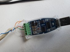
So on an interesting note, for A it lists 2 or 7, and for B it lists 1 or 8. I tried orange for A and orange/white for B, with white and green as ground, and was getting timeouts. I had set the port in device manager to both 19200 and 9600, with matching parameters in battery monitor, and nothing worked.This is what they sent me
View attachment 115175
Only 1 battery, so all dips set to off. As a last resort, I just rewired the Seplos adapter with brown/white for A, Brown for B, and green for ground, 19200 again, all dips off, and bingo, she sprang to life!
Just posting this in case it helps anyone. A standard store bought RS485 to USB had the port come up, but did not connect. Only the Seplos adapter worked for me.
Attachments
shavermcspud
Solar Enthusiast
- Joined
- Mar 12, 2020
- Messages
- 579
Pins 1 & 2 and 7 & 8 are linked on the BMS itself so most likely a mis-wire to start withSo on an interesting note, for A it lists 2 or 7, and for B it lists 1 or 8. I tried orange for A and orange/white for B, with white and green as ground, and was getting timeouts. I had set the port in device manager to both 19200 and 9600, with matching parameters in battery monitor, and nothing worked.
Only 1 battery, so all dips set to off. As a last resort, I just rewired the Seplos adapter with brown/white for A, Brown for B, and green for ground, 19200 again, all dips off, and bingo, she sprang to life!
Just posting this in case it helps anyone. A standard store bought RS485 to USB had the port come up, but did not connect. Only the Seplos adapter worked for me.
Similar threads
- Replies
- 1
- Views
- 449
- Replies
- 21
- Views
- 1K
- Replies
- 2
- Views
- 340