diy solar

diy solar

Seplos CAN BUS RS485 48v 200A 8S-16S BMS

Sparksfly30, mine is RHI inverter. This connects no problem with Seplos 10E BMS, either using GINL on BMS and user defined on inverter or SMA / AoBo.
I called Solis support yesterday after getting nowhere with raising tickets about the failure to discharge the battery once fully charged and they admitted there was an issue with battery control in the version of firmware when mine was built last year.
They did a remote firmware update and all seems to work now, so may be worth calling them.
 
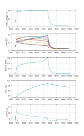
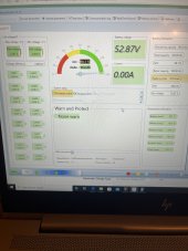
I've just tried diabling "monomer overvoltage alarm" and "total voltage overoltage alarm" while it was chargin at 10A; it seems to be working in constant voltage mode (I've set total voltage overvoltage protection to 55.2V)

View attachment 152422

View attachment 152381
Actually I don’t understand why some cells are starting with a high voltage and then dropping while others start at a lower voltage and then rise
This way the balancer will draw current from some before and from others later, being completely counterproductive

1686417152675.png
 
Last edited:
Actually I don’t understand why some cells are starting with a high voltage and then dropping while others start at a lower voltage and then rise
This way the balancer will draw current from some before and from others later, being completely counterproductive

View attachment 152448
How are you able to monitor the battery charging graphs are you using the bms or a actual monitoring unit
 
How are you able to monitor the battery charging graphs are you using the bms or a actual monitoring unit
Battery monitor to record data. Save as xls then open in Excel to convert to csv (battery monitor should do it by itself), then I process the csv with a Matlab script I’ve written.

No reason to do that anymore now that I managed to integrate the BMS with home assistant
 
Battery monitor to record data. Save as xls then open in Excel to convert to csv (battery monitor should do it by itself), then I process the csv with a Matlab script I’ve written.

No reason to do that anymore now that I managed to integrate the BMS with home assistant
How did you get the bms into home assistant? Using this integration? https://github.com/byte4geek/SEPLOS_MQTT
 
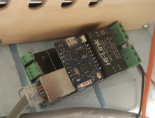
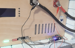
I have create a Seplos WiFi bridge that uses an ESP8266. Total cost of parts is less than $10. The device can:
1) Collect telemetry from the battery (cell voltages, voltage difference, SOC, current, total voltage) and send it to an InfluxDB
2) Turn on and off 48V heater when needed
3) Turn on and off 48V cooler (fan)
4) Enable active balancer under certain conditions
5) Exposes HTTP API that provide JSON data for the battery telemetry

It is powered directly from the 48V battery. Open source and available in GitHub. PCB can be ordered at JLCPCB. I suppose they can populate the components too and for the users will be left only to program the ESP8266.
 

Attachments

  • 1686650745580.png
    1686650745580.png
    1.5 MB · Views: 19
  • 1686650772078.png
    1686650772078.png
    2.1 MB · Views: 19
Yes, the Seplos BMS protocol is fully documented.
 

Attachments

  • SEPLOS BMS Communication Protocol_V2.0-2.pdf
    347.4 KB · Views: 71
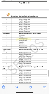
No idea. I haven't look at these values. But this is not voltage, this is state - "float charging" state. It is 1 bit. Either on or off.
 
Yes, the Seplos BMS protocol is fully documented.
Thanks,
There is actually mention of ‘floating charge’

View attachment 152742


Is this the constant voltage charge?
No idea. I haven't look at these values. But this is not voltage, this is state - "float charging" state. It is 1 bit. Either on or off.
yes, I know; it could be used to trigger an active balance for example
 
Total NOOB here. I have never seen my cells balance. It reaches 100% SoC with about 10mv difference? Guess balancing not necessary? Also is it normal for the batteries to constantly discharge without any draw from it and charge back to 100% if I look at the inverter it discharges with 12w average
 

Attachments

  • image.jpg
    image.jpg
    141.5 KB · Views: 39
  • image.jpg
    image.jpg
    138 KB · Views: 41
Total NOOB here. I have never seen my cells balance. It reaches 100% SoC with about 10mv difference? Guess balancing not necessary? Also is it normal for the batteries to constantly discharge without any draw from it and charge back to 100% if I look at the inverter it discharges with 12w average
10mv difference is about as perfect as it gets, but you are still in the flat part of the curve, you should be checking voltage differences above 3.45

the cycling you are seeing is a thing that seplos uses to help the passive balancing
 
10mv difference is about as perfect as it gets, but you are still in the flat part of the curve, you should be checking voltage differences above 3.45

the cycling you are seeing is a thing that seplos uses to help the passive balancing
10mV in the flat part doesn’t tell you anything about imbalance; you could have one cell at 20% and one at 80% withe the same voltage
That’s why I only just realised I have an imbalance, I wasn’t looking at it during the charge phase

I have 3mV in the flat part and 150mV at 56V (active balancer coming soon)
 
10mv difference is about as perfect as it gets, but you are still in the flat part of the curve, you should be checking voltage differences above 3.45

the cycling you are seeing is a thing that seplos uses to help the passive balancing
Thanks for the reply. These are shoto sdc10-box5 batteries. 5.1 nominal. Another thing I just realised now its a 2 pack parralell. The one pack charges double than the other. Dont know if rhe BMS sertings are incorrect. Should I up the voltages per cell / CV
 
10mV in the flat part doesn’t tell you anything about imbalance; you could have one cell at 20% and one at 80% withe the same voltage
That’s why I only just realised I have an imbalance, I wasn’t looking at it during the charge phase

I have 3mV in the flat part and 150mV at 56V (active balancer coming soon)
Will have a look at the charging phase. thank you
 
10mV in the flat part doesn’t tell you anything about imbalance; you could have one cell at 20% and one at 80% withe the same voltage
That’s why I only just realised I have an imbalance, I wasn’t looking at it during the charge phase

I have 3mV in the flat part and 150mV at 56V (active balancer coming soon)
did you care to read the whole sentence ?

10mv difference is about as perfect as it gets, but you are still in the flat part of the curve, you should be checking voltage differences above 3.45
 
10mV in the flat part doesn’t tell you anything about imbalance; you could have one cell at 20% and one at 80% withe the same voltage
That’s why I only just realised I have an imbalance, I wasn’t looking at it during the charge phase

I have 3mV in the flat part and 150mV at 56V (active balancer coming soon)
and added, not sure about what quality cells you are using,nor your cycle count, but good cells should get in line with 50 cycles or so
 
did you care to read the whole sentence ?

10mv difference is about as perfect as it gets, but you are still in the flat part of the curve, you should be checking voltage differences above 3.45
My message was in reply to the previous post if that wasn’t clear
 
and added, not sure about what quality cells you are using,nor your cycle count, but good cells should get in line with 50 cycles or so
A grade Eve LF280K (the ones with the double stud terminals), 80 cycles, they were in line after top balancing
I suspect a very low ‘equalisation voltage’ took them out of balance
 
Hey, can someone clarify the difference between ‘total voltage’ and ‘port voltage’?
Is total voltage the sum of each measured cell voltage, while port voltage is the voltage between cell1- and cell 16+, the difference being the busbars voltage drops?

Or is port voltage the voltage between the bms?

I noticed my charge stops when ‘port voltage’ reaches ‘total voltage overvoltage protection’ and not when ‘total voltage’ reaches is
Total voltage is always lower than port voltage during both charge and discharge
 
Last edited:
Port voltage is the voltage on the terminals in front of the battery. The BMS measures it on the P+ to P- terminals.

Total voltage is the voltage of all cells. The BMS measures it on the B+ to B- terminals.

These are almost identical if the MOSFETs are on.
 

diy solar

diy solar
Back
Top