diy solar

diy solar

Should I test every single Cell I received and other doubts/questions after Leaking Cell

Not sure how I could turn equalizing off..
What BMS do you have? Are you confusing this with balancing?

Mostly 3.43V I guess, some maybe 3.45V ? Cell 01 being 3.40V actually.
3.45Vpc with some absorption is fully charged so you are not too far off. All the weird chit always happens to cell 1 so lets not address that yet.

You 3.60V overvolt is a little low, but workable. What is your top charge voltage and what is battery voltage when cell 16 over volts?
 
What BMS do you have? Are you confusing this with balancing?


3.45Vpc with some absorption is fully charged so you are not too far off. All the weird chit always happens to cell 1 so lets not address that yet.

You 3.60V overvolt is a little low, but workable. What is your top charge voltage and what is battery voltage when cell 16 over volts?
No, the equalizing or equalization function of the inverter (or charger) I mean.

I have JK BMS, but that's only relevant for balancing. Equalization is the inverter job.

Top charge voltage and battery voltage when cell 16 over volts ? I'm not sure to be honest... I don't have any data logger setup (trying to get it to work, but need to setup other 10 systems etc ?). I think I recall 55.8 V or something like that on the bms readout).

On the inverter I think it was set to 54.0 V float and 55.0 V absorbtion. Not sure when it changes from one mode to the other though.
 
Understanding what your settings are and what is happening is crucial for considering solutions.

I don't even have a guess with no info, sorry.
It's fair ?.

I would need to be continuously supervise the charging process to monitor what exactly is going on at the exact moment when the issue happens, which includes of course having sun (or a charger connected - soon).
 
54.8v for bulk/absorption will get you above the usual 3.4 volt threshold for balancing at 3.425 volts. But it sounds like cell 16 is hitting the cell overvolt number of 3.60 so quickly that the other cells (or just cell 16) aren't getting a chance to balance. Changing the cell overvolt number to 3.65v may give it a little more time, but once cells get in that knee they tend to rise in voltage quickly. You could try bleeding voltage off of cell 16 manually to give the rest of the cells time to catch up.
 
54.8v for bulk/absorption will get you above the usual 3.4 volt threshold for balancing at 3.425 volts. But it sounds like cell 16 is hitting the cell overvolt number of 3.60 so quickly that the other cells (or just cell 16) aren't getting a chance to balance. Changing the cell overvolt number to 3.65v may give it a little more time, but once cells get in that knee they tend to rise in voltage quickly. You could try bleeding voltage off of cell 16 manually to give the rest of the cells time to catch up.
Exactly. And there isn't a huge difference above 3.55V already. It just shoots up. Balance starts at 3.42V.

Some balance happens, but even if I charge at say 2A, even then the balancer is too slow. Simply because of the steepness of the curve and the amount of charge that is moved by the balancer is tiny. But that tiny amount of charge means a significant voltage difference.

Bleeding cell 16 permanently or a one off you mean?
 
Alright ... I would have 1Ohm resistors for that (200W), so that could be an option (~ 3.5A bleed). Just no way to attach them at least on one side (unless I take the main "battery positive" connection out of the box). I'm not fan of loosely hooking up wires and then they go BANG because they weren't secured properly ...
 
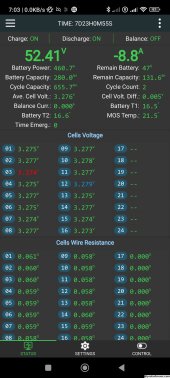
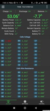
Some screenshots after a night (~ 12-14 h) of discharge.

Battery 01 seems nice and Balanced
20231025_070349_temp.jpg


Battery 02 is always the more problematic one
20231025_070326_temp.jpg

With Cell 16 being the highest (not by much though) and Cell 01 being the lowest (not by much though).

If I recall correctly Cell 16 hits Overvoltage, while Cell 01 hits Undervoltage, so it's not as simple as "just" a cell having a lower capacity value.

But also look at those difference in voltages / SOC with 2 parallel batteries: I find it quite high to have a 0.6 V difference, and 0.04-0.05 V / cell difference for such a low load.

As I said, originally I thought it was due to JK BMS HW v11 vs v10 and some Voltage Measurement tolerances. But it would seem like Battery 01 never gets fully charged, while Battery 02 always hits overvoltage on Cell 16 first.

I don't know how accurate the SOC / Capacity reported by JK BMS is, but 30 Ah difference seems like a lot (> 10% of nominal capacity).
 
The cell wire resistance values are different enough between the two batteries that it caught my eye.

Each battery has it's own cable to the charge source, right?
 
The cell wire resistance values are different enough between the two batteries that it caught my eye.

Each battery has it's own cable to the charge source, right?
Yes. Slighly different, because it's a temporary WAGO distribution block (WAGO 285-150 with several jumpers), but before I had done some measurements and they seemed quite close ...

But cell wire resistance isn't it for the balance leads ? That might result in different lengths but I don't believe 15 mOhm difference ! I used 2.5 mm2 wires to a fused terminal block (7.5 A fuse on each sensing wire), then the original JK BMS wire bundle. The 2.5mm2 might have been somewhat different, but that's already between Cell 01 and Cell08. Which is not really shown in the JK BMS output.

Why the huge difference between the 2 batteries I don't know.
 
Maybe higher SOC = lower internal resistance ? Then maybe that's reflected in the "cell wire resistance" ?
 
Back
Top