diy solar

diy solar

Signature Solar EG4 6.5K Off-Grid Inverter | 6500EX-48

The first thing that I would do is remove the cables and change the setting from EG4 to User - see if you can make it so the inverter stops shutting down.
Yeah, that's the second thing I'd do.... it happened to me too... first - check the cable carefully - both ends - to make sure the rj45 connector is crimped on cleanly and completely. Then, make sure it is seated properly in the rj45 jacks on both ends. I have noticed that the original cable shipped with the unit can be "jiggled" when plugged in, indicating that it sometimes loses connection. I made my own new cable and it has worked flawlessly since.
 
Think the rule of thumb is 5x to7x running amps for inductive loads. My pump running after first 2 seconds is 5.8a or 1400w like clockwork. Starting inrush is always just over 37a so approx 9000 watts.

My neighbor bought a harbor freight ac/dc meter for $99 that measures ac inrush. It was not far off from my fluke, about .25 amp.

Would love to have someone prove that these inverters in split phase can start a deep well pump. Understand that my 9kw surge is under total capacity of 13kw but surge power overall is no joke.
I am having the same issue with my pair of 6500's in split phase but mine is above ground - a 2 hp well pump.
It simply will not start. When it tries, all the voltage drops on both legs enough to dim the lights and cause my ups to beep (like a power hit on grid).... then bounces back to normal. Interestingly, no faults on the inverters at all.

Previously, I had a single es5000 running the pump. It worked fine, except when the pump started - and it did start and run properly. The inverter beeped, said 100% load for a split second, then continued on it's merry way. I definitely need to get a meter to check inrush current, but I have 30 amp breakers and they are not tripping.

The SPECS of my pump are as follows: HP: 2.0 / F.L.A 8.3 / S.F 1.4 / S.F.A 12 / Volts: 230 / HZ 60.
So I read this as:
The Full Load Amperage (FLA) - the amount of current the motor is designed to draw at the rated horsepower) = 8.3.
The Service Factor Amps (SFA) - the overload capacity of the motor. Ultimately, SFA indicates how much your motor can run without sustaining damage = 12
The S.F. is a multiplier applied on top of FLA (ok, to be technical it is applied to horsepower.... I don't make a distinction but some in this forum will) = 1.4 - I don't know how this affects the power calculations.

Unfortunately, it does not state what the inrush / starting current will be.
Assuming that it is 7x (worst case as you state above) of the FLA (8.3A) - that would equate to be 58.1 amps. - how many watts is that????
Is that under the 13KW surge rated? I expect that is the reason the pump is not starting.

Thoughts?
 
it is because the connection is between RS232 and RS465 - if you look at the pin explanations, it matches - if you use a straight through ethernet cable, they are not going to meet as needed.
Hmmm.... OK. You are saying one end is RS232 and the other end is RS465.

That leads to my next question: Why would they try to connect RS232 and RS465 via a passive cable? You can make it work but in the RF-noisy environment of an inverter, I doubt it is very reliable. An even more basic question is why would they put a different level 1&2 protocol on their battery than on their inverter?

BTW: For an RF noisy environment, RS485 is far superior.
In the post I was responding to it said RS465. I assume he meant RS485. I should have responded like this:
I assume you mean RS485. You are saying one end is RS232 and the other end is RS485?

That leads to my next question: Why would they try to connect RS232 and RS485 via a passive cable? You can make it work but in the RF-noisy environment of an inverter, I doubt it is very reliable. An even more basic question is why would they put a different level 1&2 protocol on their battery than on their inverter?

BTW: For an RF noisy environment, RS485 is far superior.
 
I am having the same issue with my pair of 6500's in split phase but mine is above ground - a 2 hp well pump.
It simply will not start. When it tries, all the voltage drops on both legs enough to dim the lights and cause my ups to beep (like a power hit on grid).... then bounces back to normal. Interestingly, no faults on the inverters at all.

Previously, I had a single es5000 running the pump. It worked fine, except when the pump started - and it did start and run properly. The inverter beeped, said 100% load for a split second, then continued on it's merry way. I definitely need to get a meter to check inrush current, but I have 30 amp breakers and they are not tripping.

The SPECS of my pump are as follows: HP: 2.0 / F.L.A 8.3 / S.F 1.4 / S.F.A 12 / Volts: 230 / HZ 60.
So I read this as:
The Full Load Amperage (FLA) - the amount of current the motor is designed to draw at the rated horsepower) = 8.3.
The Service Factor Amps (SFA) - the overload capacity of the motor. Ultimately, SFA indicates how much your motor can run without sustaining damage = 12
The S.F. is a multiplier applied on top of FLA (ok, to be technical it is applied to horsepower.... I don't make a distinction but some in this forum will) = 1.4 - I don't know how this affects the power calculations.

Unfortunately, it does not state what the inrush / starting current will be.
Assuming that it is 7x (worst case as you state above) of the FLA (8.3A) - that would equate to be 58.1 amps. - how many watts is that????
Is that under the 13KW surge rated? I expect that is the reason the pump is not starting.

Thoughts?
What is your pv input into your inverters. It can only put out what the inverters recieve. If it’s not seeing 13kw then it would draw down voltage.
 
Hmmm.... OK. You are saying one end is RS232 and the other end is RS465.

That leads to my next question: Why would they try to connect RS232 and RS465 via a passive cable? You can make it work but in the RF-noisy environment of an inverter, I doubt it is very reliable. An even more basic question is why would they put a different level 1&2 protocol on their battery than on their inverter?

BTW: For an RF noisy environment, RS485 is far superior.
All good questions. I don't have the answer to either of those although I suspect they are "overloading" a rs232 port on an existing hardware solution and using it as rs465, so not actually mixing protocols. As an engineer, I would have designed this a little differently, but that is a completely different discussion. FWIW, it seems pretty reliable (or reliable enough for the BMS's to communicate with the firmware)
 
I am having the same issue with my pair of 6500's in split phase but mine is above ground - a 2 hp well pump.
It simply will not start. When it tries, all the voltage drops on both legs enough to dim the lights and cause my ups to beep (like a power hit on grid).... then bounces back to normal. Interestingly, no faults on the inverters at all.

Previously, I had a single es5000 running the pump. It worked fine, except when the pump started - and it did start and run properly. The inverter beeped, said 100% load for a split second, then continued on it's merry way. I definitely need to get a meter to check inrush current, but I have 30 amp breakers and they are not tripping.

The SPECS of my pump are as follows: HP: 2.0 / F.L.A 8.3 / S.F 1.4 / S.F.A 12 / Volts: 230 / HZ 60.
So I read this as:
The Full Load Amperage (FLA) - the amount of current the motor is designed to draw at the rated horsepower) = 8.3.
The Service Factor Amps (SFA) - the overload capacity of the motor. Ultimately, SFA indicates how much your motor can run without sustaining damage = 12
The S.F. is a multiplier applied on top of FLA (ok, to be technical it is applied to horsepower.... I don't make a distinction but some in this forum will) = 1.4 - I don't know how this affects the power calculations.

Unfortunately, it does not state what the inrush / starting current will be.
Assuming that it is 7x (worst case as you state above) of the FLA (8.3A) - that would equate to be 58.1 amps. - how many watts is that????
Is that under the 13KW surge rated? I expect that is the reason the pump is not starting.

Thoughts?
These inverters, in split phase, are supposed to surge up to 26kw for a short time I believe. How many batteries and what size cables do you have?
 
@howiegrapek how much battery capacity do you have on these?
I have 6 x eg4 batteries all connected in the rack in parallel …. 30 kwh approx. 00 2/0 (2 ott) cables between inverters and bus bar and 00 4/0 (4 ott) between bus bar and battery rack bus bars. It should handle that much power and then some.
 
I have 6 x eg4 batteries all connected in the rack in parallel …. 30 kwh approx. 00 2/0 (2 ott) cables between inverters and bus bar and 00 4/0 (4 ott) between bus bar and battery rack bus bars. It should handle that much power and then some.
And the wiring from the inverters 4ga? That should start that well pump. Almost sounds like the draw is on only one of the inverters.
 
Last edited:
And the wiring from the inverters 4ga? That should start that well pump. Almost sounds like the draw is on only one of the inverters.
ok, so what would happen if only one of the two inverters had pv connected…. 2kw and 4kw on pv1 /pv2 respectively and if inverter 2 had no solar turned on. I would expect the draw to properly come from battery…. would that cause draw on box 1 only? the settings are solar first, then battery, then grid…. of course this is all off grid… no connection to it.
 
ok, so what would happen if only one of the two inverters had pv connected…. 2kw and 4kw on pv1 /pv2 respectively and if inverter 2 had no solar turned on. I would expect the draw to properly come from battery…. would that cause draw on box 1 only? the settings are solar first, then battery, then grid…. of course this is all off grid… no connection to it.
It will all work just fine. If the sun is shining, the inverter with the solar might draw a little less from the battery.... but any excess power will go to the battery and be available for both.
 
It will all work just fine. If the sun is shining, the inverter with the solar might draw a little less from the battery.... but any excess power will go to the battery and be available for both.
i would think so too. ya midday and full sun. i don’t understand why it might be acting this way or why it seems like only one inverter is being drawn on. it’s a mystery. open for suggestions.
 
hi,
Do these support TOU settings. I see some configuration in the manual but not sure. I basically want to charge my battery after 9 p.m and not during peak hours

thank you
 
ok, so what would happen if only one of the two inverters had pv connected…. 2kw and 4kw on pv1 /pv2 respectively and if inverter 2 had no solar turned on. I would expect the draw to properly come from battery…. would that cause draw on box 1 only? the settings are solar first, then battery, then grid…. of course this is all off grid… no connection to it.
I would say you need more pv panel input.
ok, so what would happen if only one of the two inverters had pv connected…. 2kw and 4kw on pv1 /pv2 respectively and if inverter 2 had no solar turned on. I would expect the draw to properly come from battery…. would that cause draw on box 1 only? the settings are solar first, then battery, then grid…. of course this is all off grid… no connection to it.
the only difference between your system and mine is the amount of pv coming in
 
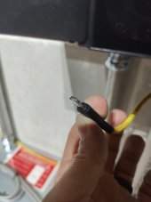
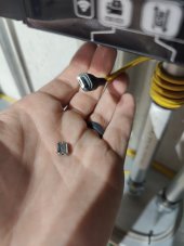
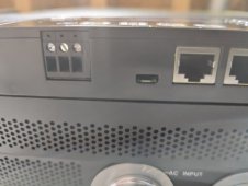
Has anyone ever seen anything like this? I've never seen this happen to any device ever - cell phone, camera, or anything else with a micro USB port.

Check this out:

1661796685147.jpeg 1661796769110.jpeg 1661796799586.jpeg

I was troubleshooting some issues that I was having with Solar Assistant, and in disconnecting the Micro USB cable, that happened. ?

Has this happened to anyone else on their 6500Ex?
 
Back
Top