diy solar

diy solar

Signature Solar's new EG4 6000 120/240V inverter

Copy/paste from my profile:
2 - EG4 6000EX-48HV 120/240V inverters (https://signaturesolar.com/eg4-6k-off-grid-inverter-6000ex-48hv)
6 - EG4 LifePower4 lithium batteries (https://signaturesolar.com/eg4-lifepower4-lithium-battery-48v-100ah)
32 - Solarever 410W Half-Cell Mono PERC solar panels (https://signaturesolar.com/solarever-410w-half-cell-mono-perc-solar-panel-black-full-pallet-31)

So that's about 14.5kW worth of panels. I've seen solar production as high as about 12,000 watts, but as you can see in the pictures, my panels are laid virtually flat on the ground and we are already six weeks past the summer solstice.

I haven't run it long enough to know the exact numbers, but 30kWh won't even come close to charging the tesla in a single go, but that's mostly due to my driving patterns. I have a 140 mile round trip work commute twice a week (work from home the other three days). My 2020 model 3 long range has a 75kWh IIRC, and it takes right about 60% of the battery to do that 140 mile round trip, of which about 80% of it is at 80mph here in texas. That's a raw 45kWh to put back into the battery not counting the inverter conversion losses, the tesla onboard charger losses, nor the battery chemistry losses.

So I've used purely the batteries right when I come home and it's nearly dark, or already dark. I can get about 45-50% of the required recharge put back in, then the following day, I finish the charging with solar.
Hi thanhrodke: I read this thread with great interest as I received the 6000EX last week and have not been able to commission it to run my Tesla universal mobile charger nor my Juicebox EV charger. Hopefully you'll see my post, since it's been a while. I've posted my issues on another thread, but am re-posting it here since you're successfully charging your Tesla.

My setup:
1 - EG4 6000EX
3 - EG4 LifePower4 batteries
Sorry, fat fingered the wrong key and it posted while typing...
+ 5s/2p 375W REC PV panels
Wiring diagram attached.

The system is off grid powering my EV chargers via a critical loads panel. Neither of my chargers will work due to ground faults or the Tesla UMC throwing adapter faults (the "T" LED is flashing red twice = loss of ground, the "T" LED is flashing 5 times = adapter errors).

I tried multiple grounding and bonding configurations and only after bonding the neutral/ground in my output panel, the Tesla charger worked although it current limited at 8A due to the above errors. I also had to bond the output panel ground to the main service ground for the Tesla charger to work. However, the charging stopped in < 1 hour with a code 07 fault "overload error." Wondering if you bonded your NG in your AC output panel? Did you connect your ground rod directly to the AC input ground as you suggested in post #139 (I understand you're not using the AC in).

Thanks in advance for your help!
 

Attachments

  • EG4 6000ex wiring diagram.pdf
    184.7 KB · Views: 16
check to see if the EG4-6000EX is bonding N-G internally via a relay (check resistance while inverter ON/OFF)

Does it charge with PV disconnected ? My EVSE (EV-charger for a Boltev) is also stopping, with inverter (MPP-U5648GK) showing "over current" fault. It works fine with PV disconnected (on battery only). But the U5648 is a non-isolated inverter, and I believe there is a current leak, possibly via PV(-) grounded somewhere.

I also think the N-G bond in the CriticalLoad-panel is not correct, because there would be 2x N-G bonds (CriticalLoad-panel & Main-panel). I would run a new N line to the Main to have just one N-G bond

The U54648 manual has this warning:
"WARNING: Because this inverter is non-isolated, only three types of PV modules are acceptable: single crystalline, poly crystalline with class A-rated and CIGS modules. To avoid any malfunction, do not connect any PV modules with possible current leakage to the inverter. For example, grounded PV modules will cause current leakage to the inverter. When using CIGS modules, please be sure NO grounding"
 
<Warning: RANT MODE ON>
Why can't these $%$#!@& manufacturers give us information on the grounding of the inverter!!! Why do we have to reverse engineer their product to get this basic information? This information is fundimental to understanding how the inverter should be safely wired and yet EG4, MPP and Growatt all leave this critical information out of their manuals. It is nearly criminal negligence!!

Ok... I feel better now.
<RANT MODE OFF>


Thanks for the pics!! Very helpful.

The circled screw is almost certainly a Bonding screw.

View attachment 113596


The interesting thing is that I count 5 power relays.....
View attachment 113598

Based on the number of relays, I am almost positive the inverter is doing dynamic bonding. These are the type of relays used for the internal transfer switch for all of the low-cost AIO inverters. What I am scratching my head on is what all 5 are for.
  1. Hot 1
  2. Hot 2
  3. Neutral
  4. Bonding
  5. ????
Someone might suggest the fifth is to switch ground, but there is no need to switch ground, it is an unsafe idea to switch ground, and I don't know of any other inverter that switches ground


Havings said all that, based on everything so far in this thread, this is my best guess at a model for the inverter.

View attachment 113599
So I have read through all 9 pages of this thread. (excellent job, you all did with the write-ups and testing). I currently have an inverter (PowMr unit) that has the in-neutral and out-neutral bonded in both modes, so when I have the unit plugged in to Grid power but it is operating in battery mode, I get this weird flicker on the LED lights in the house (Probably a phasing issue where they're overlapping). (and note that the lights don't flicker when I have the AC-In unplugged). I would think that you would want to have the neutrals to be dynamically switched (connected in pass through and disconnected in battery mode). Is this correct, and also, was there ever a definitive conclusion to how the 6000ex functions? I really like the specs of this unit for my Air compressor, saw, Edger, etc that are high-current loads. But I hate these flickering lights.
 
So I have read through all 9 pages of this thread. (excellent job, you all did with the write-ups and testing). I currently have an inverter (PowMr unit) that has the in-neutral and out-neutral bonded in both modes, so when I have the unit plugged in to Grid power but it is operating in battery mode, I get this weird flicker on the LED lights in the house (Probably a phasing issue where they're overlapping). (and note that the lights don't flicker when I have the AC-In unplugged).
There are many things that could be causing the flicker. It could be a bonding issue, but if I had to bet with just the info provided, I would bet not.
I would think that you would want to have the neutrals to be dynamically switched (connected in pass through and disconnected in battery mode). Is this correct,
For inverters, there are basically two ways to deal with the bonding. Both methods work, but each have different areas they work best in.

1) Common Neutral and No bonding.
On many inverters, the input neutral is the same electrical circuit as the output neutral at all times. On these inverters, they never do N-G bonding. Since the neutral is never switched, they count on the NG-Bond of the input circuit for all situations. (In my opinion, this is the best way to do it for stationary systems.)

2) Switched Neutral and Dynamic bonding.
On many inverters, the input neutral is disconnected from the Output neutral when in battery mode. This Isolates the output circuit from the bond from the input circuit so when the neutrals get disconnected, the inverter creates a new NG bond on the output. (In my opinion, this is the best way to do it for mobile installations where the shore power and its bond may or may not be there.)

I have seen some inverters that do the neutral switching and don't do the dynamic bonding. These units are difficult to work with because they don't work well in any situation.

and also, was there ever a definitive conclusion to how the 6000ex functions?
Yes and no. In the announcement Video the EG4 released about the changes to bonding, they implied that at least from a grounding and bonding point of view the 6000 and 6500 behaved the same. However, since I have not got my hands on one, I am still a little fuzzy on exactly what the internal architecture looks like. In particular, I can not tell if the output transformer is in the circuit as an autotransformer or not.
I plan on getting this sorted out, but with my personal schedule, it is likely to be several weeks.
 
I currently have an inverter (PowMr unit) that has the in-neutral and out-neutral bonded in both modes, so when I have the unit plugged in to Grid power but it is operating in battery mode, I get this weird flicker on the LED lights in the house (Probably a phasing issue where they're overlapping). (and note that the lights don't flicker when I have the AC-In unplugged)
which PowMr unit specifically ?
 
There are many things that could be causing the flicker. It could be a bonding issue, but if I had to bet with just the info provided, I would bet not.

For inverters, there are basically two ways to deal with the bonding. Both methods work, but each have different areas they work best in.

1) Common Neutral and No bonding.
On many inverters, the input neutral is the same electrical circuit as the output neutral at all times. On these inverters, they never do N-G bonding. Since the neutral is never switched, they count on the NG-Bond of the input circuit for all situations. (In my opinion, this is the best way to do it for stationary systems.)

2) Switched Neutral and Dynamic bonding.
On many inverters, the input neutral is disconnected from the Output neutral when in battery mode. This Isolates the output circuit from the bond from the input circuit so when the neutrals get disconnected, the inverter creates a new NG bond on the output. (In my opinion, this is the best way to do it for mobile installations where the shore power and its bond may or may not be there.)

I have seen some inverters that do the neutral switching and don't do the dynamic bonding. These units are difficult to work with because they don't work well in any situation.


Yes and no. In the announcement Video the EG4 released about the changes to bonding, they implied that at least from a grounding and bonding point of view the 6000 and 6500 behaved the same. However, since I have not got my hands on one, I am still a little fuzzy on exactly what the internal architecture looks like. In particular, I can not tell if the output transformer is in the circuit as an autotransformer or not.
I plan on getting this sorted out, but with my personal schedule, it is likely to be several weeks.

Look forward to your findings on the EG4 6000EX-48HV
 
There are many things that could be causing the flicker. It could be a bonding issue, but if I had to bet with just the info provided, I would bet not.

For inverters, there are basically two ways to deal with the bonding. Both methods work, but each have different areas they work best in.

1) Common Neutral and No bonding.
On many inverters, the input neutral is the same electrical circuit as the output neutral at all times. On these inverters, they never do N-G bonding. Since the neutral is never switched, they count on the NG-Bond of the input circuit for all situations. (In my opinion, this is the best way to do it for stationary systems.)

2) Switched Neutral and Dynamic bonding.
On many inverters, the input neutral is disconnected from the Output neutral when in battery mode. This Isolates the output circuit from the bond from the input circuit so when the neutrals get disconnected, the inverter creates a new NG bond on the output. (In my opinion, this is the best way to do it for mobile installations where the shore power and its bond may or may not be there.)

I have seen some inverters that do the neutral switching and don't do the dynamic bonding. These units are difficult to work with because they don't work well in any situation.


Yes and no. In the announcement Video the EG4 released about the changes to bonding, they implied that at least from a grounding and bonding point of view the 6000 and 6500 behaved the same. However, since I have not got my hands on one, I am still a little fuzzy on exactly what the internal architecture looks like. In particular, I can not tell if the output transformer is in the circuit as an autotransformer or not.
I plan on getting this sorted out, but with my personal schedule, it is likely to be several weeks.
Your posts are so helpful. I've just done some re-wiring in prep for adding a permanent set up. I noticed that a GFCI that is fed from the OUT of my PowMr is tripping when I plug in a UPS battery backup into it (my internet equipment). Other 3-prong items don't trip this same GFCI. And that UPS does NOT trip a grid-connected GFCI. There is SO much to discover with these things!

So if I am reading all of this correct, what you're trying to understand about the 6000ex is the purpose of the transformer. Whether or not that transformer is integral to the inverter doing its inverting function **OR** if it's only acting as an autotransformer to provide the neutral for the 120v output legs?

Forgive me if this is a naive question, but if the transformer is ONLY functioning as an autotransformer, would that indicate that this is not, in fact, a Low-Frequency inverter? But rather a High-Frequency inverter with a Built-In autotransformer (for convenience rather than having to have a separate autotransformer)? The reason I ask is that I don't see any of the marketing materials listing this as a low-frequency inverter. I would think that would be something to market if it actually was a LF inverter.
I am confident the transformer is used when in battery mode. That's not my question. What I don't know is if the secondary is in parallel with the grid in passthrough mode (Acting as an autotransformer).

I had convinced myself that it was in parallel but now I'm not sure.
 
I currently have an inverter (PowMr unit) that has the in-neutral and out-neutral bonded in both modes,
does "bonded" here mean NG connected ? were these measurement done with the unit off and disconnected ? am wondering if there is an NG relay.
so when I have the unit plugged in to Grid power but it is operating in battery mode, I get this weird flicker on the LED lights in the house (Probably a phasing issue where they're overlapping). (and note that the lights don't flicker when I have the AC-In unplugged).
sounds like there are multiple NG bonds. The AC-IN has NG back at the main panel and the house circuits also have NG at the main panel.
I would think that you would want to have the neutrals to be dynamically switched (connected in pass through and disconnected in battery mode).
it depends on the connection to the house circuit(s). No matter how, there should only 1 NG bond
 
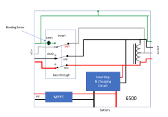
OK folks, after a bunch of research, I can say with confidence that the 6000 EX is modeled like this:

1681361060787.png

A few key things about this diagram.

* The transformer is ONLY an autotransformer. Previously I had not even considered this as a possibility so it was a bit of a surprise when I discovered it.

* The autotransformer is always on the output (including in pass-through mode). Before anyone freaks out about that, there are a couple of things that are not shown in the diagram above:
1) There are current sensors on the hot lines right before the autotransformer.​
2) There are relays on both hot lines right before the transformer.​
The inverter will cut the current by opening the relays if the current differential gets too high.

* The diagram above shows the bonding screw in place but, EG4 has clearly indicated the units are no longer shipping with the screw installed.

* Notice that the same relay that disconnects the neutral-in from the neutral-out also generates the NG bond. This means that the new "stationary firmware" will work correctly even if the bonding screw is in place. (The new firmware leaves the neutral connected at all times so the N-G bond is never created)
 
Last edited:
I am rarely up on new stuff, but happened to need inverters for a new install. So we canceled our order for two EG4 6500 units at Signature Solar and got two of the 6000s.

Anyhow, I pulled open the left side of the case last night, and it looks to me like there's a big fat transformer in there, which obvious explains the increased weight over the 6500.

I was actually into it chasing what is a small metal vibration buzzing when under the right load. I am assuming there's a piece of sheet metal that just needs a little tweaking. but when I hit the right side of the unit, there's a security sticker over one of the screws, so I got this shot by bending the sheet metal out a bit. My second unit is silent ender all conditions.
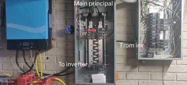
PLEASE COULD YOU SHOW ME TO VERIFY MY INSTALL DIY WILL BE CORRECTLY DONE with a slow motion video of your setup of wiring to main circuit breaker panel??? thanks if you can . . . .I have the eg4 6000ex just wanting to install the one for now
 
PLEASE COULD YOU SHOW ME TO VERIFY MY INSTALL DIY WILL BE CORRECTLY DONE with a slow motion video of your setup of wiring to main circuit breaker panel??? thanks if you can . . . .I have the eg4 6000ex just wanting to install the one for now
That should help, 'same inverter'
 

Attachments

  • IMG_20221226_190607__01__01__01.jpg
    IMG_20221226_190607__01__01__01.jpg
    336 KB · Views: 31
PLEASE COULD YOU SHOW ME TO VERIFY MY INSTALL DIY WILL BE CORRECTLY DONE with a slow motion video of your setup of wiring to main circuit breaker panel??? thanks if you can . . . .I have the eg4 6000ex just wanting to install the one for now
Sorry for my late reply, did the picture from @42OhmsPA help?
 
Back
Top