diy solar

diy solar

Signature Solar's new EG4 6000 120/240V inverter

I am not a certified electrician, but have been wiring stuff for 30+ years, including several remodels and my current house. I understand NEC specs and requirements, I read 1 gauge wire as being 130 amp rated with 75C insulation rating.

each EG4-6000 unit can charge at a maximum of 120amps, so we are under that 130amp rating.

from a charging standpoint, each EG4 LifePower 48V battery is rated at 100amps individually, so the rack of six batteries could take 600amps max charging rate. the two inverters can output a total of 240amps, so at maximum, they can do 40% of the combined battery's capabilities, so no worries there. that's a .4C charge rate, which is a little higher than a lot of batteries are rated, which is .3C.

from a discharge standpoint, the batteries are also rated at 100amp each as well, with a recommended 30amp continuous rating. when charging my tesla, and both units are running at that 98-102% level for an hour or more, the cables certainly get warm, but not even too close to grip firmly. it's generally understood that a human can hold something that's 60C (140F) for five seconds without burning, so my cable had to be way cooler than that. I don't have Will's super cool Klein temp gauge, but I do have the USB-C model on the way (here in a few weeks).

as to the output connections from the inverter to the breaker panel, as you noted, the manual suggests 10gauge, and that supports the inverters rating of 6000watts. 6000watts across 240 volts is 25 amps, and 10 gauge is generally rated at 35 amps with a 75C insulation. note that the manual recommends 90C rated wire, which is satisfied by your typical romex style wire, service cord (SO), or even individual THHN/THWN insulated wires. at those temps, 10ga wire is rated at 40amps, but the NEC limits the operating temps of the conductors to 60C, so that derating limits the wire to 30amps. in my case, I had some leftover 6gauge laying around (rated 55amps at 60C), so I just used that. it just had to be bigger than 10gauge. I used 40 amp breakers, as that's what the manual lists for the AC in breaker, but there's no AC out breaker size listed. if using 10ga wire, I think the correct breaker would be 30amp breakers.

I will take a moment here and point out the worst acronym that you will ever come across when doing any kind of construction, wiring, plumbing, etc., and that's "AHJ". it stands for "authority having jurisdiction". that means that regardless of the national electric code (NEC), standard plumbing code, or any other widely-known best practice, you've got some local bureaucrat that can override anything they want in your particular location. this could affect anything in your install, such as wire and breaker sizes, clearance in front of and around your inverters, how high off the ground they have to be placed and more. while it never gets to this, they could even dictate what specific brands are allowed within their jurisdiction. at the end of the day, your local inspector has so sign off on the install, or it can't be put into production. it's honestly irritating as all get out, and you different standards in different locations. thankfully, the majority of the country sticks to the NEC, but there's still so much left to interpretation in the NEC code. bottom line: consult your AHJ before diving into making any install permanent at your house.

hopefully with all of the math and stats and ratings in there, I did not mess anything up. please correct me if I did.
Thanks again, you certainly seem to have a handle on things electrical. I was an electronics technician for almost 30 years, but I'm still catching up on actual electrical issues. The distance between my inverter and critical loads panel would be about 65ft, and in conduit, so 10ga probably would be pushing it. I'll probably use 8ga, which obviously costs more, but I want to do it safely.

I'm not going to run as much as you are, my system is for 120V critical loads for now. Might add a few smaller 240V loads later. I would have the input of the inverter tied to our main service panel, so that utility can charge the battery and/ or power the loads when need be. My concern for the wiring was in regards when the inverter is in bypass mode; that more current than the inverter is capably putting out at max inverting power might be passing through, and that might be more than 40A, so 10ga would be a no-go. Would I be pulling 40A at any one time? Probably not, but, 8ga should cover such a possibility.
 
Last edited:
I love discussions like that that force the numbers to be worked. and as I said, that schneider unit is a really amazing unit, and it is very likely more efficient across the board. those efficiencies could completely negate the pure dollar savings over going with an all EG4 ecosystem.

Your missing the part where you will need 3 or more EG4's to match the service life of a single XW, which has over 16 years of field data.
 
Your missing the part where you will need 3 or more EG4's to match the service life of a single XW, which has over 16 years of field data.
@Solar Guppy, that's a totally fair and possibly accurate reply, but I am willing to support the new guy. we obviously don't have the long term data on these EG4 inverters, but with the five year warranty when used with EG4 batteries, I have little concern for long-term reliability. certainly a solid counter to that statement is asking will they even be around to support the warranty, and the answer is that I don't know. but a risk I am willing to accept when a stable company like signature solar is providing the support. that said, I feel that it's also fairly presumptive to assume that the EG4 service live will be 1/3 of the schneider. someone somewhere likely made these exact same claims against schneider 16 years ago when the XW series was released. no doubt the schneider is an awesome inverter, and I love schneider products, always have.

continuing, since most electronics failures are related to infant mortality issues, if these run several years with no issues, then there's little reason they won't run several more after that. but for sure, we don't know what the bathtub curve is. assuming the XW has a service life of 15 years (to make my math work nicely), if I get 7.5 years instead of 5 years out of these, then I only bought two of them in your example, and it's still pretty much a wash financially and utility.

there's also the likelihood that inverter prices will go down over time for a given capacity and feature set. solar is just getting reasonably affordable for DIYers and homeowners, plus the new 30% tax credit will fast forward installation, demand and thus innovation. I will build everything related to this myself, and my labor won't be worth much per hour if one needs replacing. it might cost some youtubers some ad revenue, but not much.

lastly, I will need four of these units to carry my peak load and heavy motor startup needs. that's $8,000 cost difference across four units. even on a decent sized install as I will have, that's another 15% cost. assuming the warranty is in place, that difference would cover six replacement units beyond that five year mark.

(no maths done here factor in the rebate, which affects all of the times and dollars the same)
 
Last edited:
Thanks again, you certainly seem to have a handle on things electrical. I was an electronics technician for almost 30 years, but I'm still catching up on actual electrical issues. The distance between my inverter and critical loads panel would be about 65ft, and in conduit, so 10ga probably would be pushing it. I'll probably use 8ga, which obviously costs more, but I want to do it safely.

I'm not going to run as much as you are, my system is for 120V critical loads for now. Might add a few smaller 240V loads later. I would have the input of the inverter tied to our main service panel, so that utility can charge the battery and/ or power the loads when need be. My concern for the wiring was in regards when the inverter is in bypass mode; that more current than the inverter is capably putting out at max inverting power might be passing through, and that might be more than 40A, so 10ga would be a no-go. Would I be pulling 40A at any one time? Probably not, but, 8ga should cover such a possibility.
I often use southwire's voltage drop calculator when figuring stuff like this out: https://www.southwire.com/calculator-vdrop

anyhow, I show only about a 1% difference in voltage loss, and that's at a full 25 amps. the values are even lower than that at less amperage.

wire loss is not really material at short distances, but with long distance, it gets huge. for example, I need to run power to a greenhouse that's about 1,000 foot away from the power supply. for cost effectiveness, I'll run 2-2-2 URD. but at that distance, a cable that's ordinarily rated for about 90 amps is good for like 11amps with the standard 3% voltage drop. it's not out of the question to allow up to a 10% drop for general purpose stuff like lighting and heating, but some stuff might get upset with only 105VAC or so. but I will just use it for overhead led lighting. I am going big so that I can run a small tool if needed.
 
I need to run power to a greenhouse that's about 1,000 foot away from the power supply. for cost effectiveness, I'll run 2-2-2 URD.
Wow, 1000ft? That's gonna be a pain in the wallet!

So, were you implying me running 10ga might be okay at 65ft? Well, actually 130ft if you count the distance to and from the inverter.
 
Wow, 1000ft? That's gonna be a pain in the wallet!

So, were you implying me running 10ga might be okay at 65ft? Well, actually 130ft if you count the distance to and from the inverter.
Yeah, that will be like a $1,300 roll of wire, plus trenching. But I need to run water down there as well, so I get a 2-for-1 deal on the trenching. :)

And yes, 10ga would be fine for 65ft at 25 amps. It's just under 3% voltage drop at that distance. And you don't count round trip when calculating voltage drop. AC electricity can be thought of as more of a push/pull system than a unidirectional flow like DC is. That's probably a bad analogy, but that's how I think of it.

This isn't official electrical advice or anything, I'm just reading the charts and running the voltage drop calculator.
 
Last edited:
Yeah, that will be like a $1,300 roll of wire, plus trenching. But I need to run water down there as well, so I get a 2-for-1 deal on the trenching. :)

And yes, 10ga would be fine for 65ft at 25 amps. It's just under 3% voltage drop at that distance. And you don't count round trip when calculating voltage drop. AC electricity can e right of as more of a push/pull system than a unidirectional flow like DC is. That's probably a bad analogy, but that's how I think of it.

This isn't official electrical advice or anything, I'm just reading the charts and running the voltage drop calculator.
Thanks. Maybe I'll do 10ga after all.

I actually thought a 1000ft of 2-2-2 would be a lot more than that, like over $2-3/ft. You must've got a great deal on the wire. I'm assuming you'd be putting that in conduit what with a water line also in the trench?
 
Thanks. Maybe I'll do 10ga after all.

I actually thought a 1000ft of 2-2-2 would be a lot more than that, like over $2-3/ft. You must've got a great deal on the wire. I'm assuming you'd be putting that in conduit what with a water line also in the trench?
I'll do aluminum, so a lot cheaper. Copper could easily be over $5/ft these days.

The cable is rated for direct burial, so it's going in the trench with a single run of poly pipe, so there won't be any joints/connections anywhere in the trench.
 
Thank you for all the great information.

Do you have a Neutral-Ground bond anywhere on the *output* side of the inverter? If you don't, could you do us a favor and measure voltage between neutral and ground in both pass-through and inverter mode? I would like to know what it is doing with NG bonding. (At least some Tesla chargers require an N-G bond to operate so my guess is you will find very little voltage between Neutral and ground.

If you get a chance, it would be great if you could measure the resistance between input neutral and output neutral while the inverter is not hooked up at all.
Okay, just tested this!

Neutral and ground are definitely bonded at the inverter.

I first tested at my secondary breaker panel where the inverters are connected, and there was no registerable resistance across neutral and ground using a Klein multimeter. Meter was reading zero.

I then checked my upstream breaker panel and it's a passthrough panel, which only a single grounding bus in it. It's the grid service entry point to my shop, so that's expected. I turn off the main 200amp breaker in that panel when I'm writing with the inverters.

I then pulled the first inverter ground at the inverter itself and no resistance there either across neutral and ground. But then I remembered the second one was still connected, so I disconnected that ground as well.

So with all grounds (aka green wire, aka bare wire) disconnected everywhere and the inverters disconnected from solar and the batteries (I have no grid input during testing), the inverters still showed zero resistance across the neutral and ground terminals. Just in case there was a magic relay in the system somewhere, I also tested with the inverter running when there was only solar input, and also when there was solar input and AC output. Neutral and ground are connected in all operational scenarios.

It should be noted that we also had lights flickering when the solar input got up around 4-5,000 watts, but that seems to have gone away by disconnecting the ground at the inverter. I'm sure there was a small ground loop caused by the fact that I'm doing my testing in a downstream panel. I don't think an ordinary install would have this behavior as the inverter would be the source of the neutral/ground bond, and all downstream panels would have separate neutral and ground bus bars.

Hope this helps!
Yes. Very helpful.

One more test if it is not too late: If there is nothing hooked up to the inverter, is there continuity between input and output neutral?
 
Okay, just tested this!

Neutral and ground are definitely bonded at the inverter.

I first tested at my secondary breaker panel where the inverters are connected, and there was no registerable resistance across neutral and ground using a Klein multimeter. Meter was reading zero.

I then checked my upstream breaker panel and it's a passthrough panel, which only a single grounding bus in it. It's the grid service entry point to my shop, so that's expected. I turn off the main 200amp breaker in that panel when I'm writing with the inverters.

I then pulled the first inverter ground at the inverter itself and no resistance there either across neutral and ground. But then I remembered the second one was still connected, so I disconnected that ground as well.

So with all grounds (aka green wire, aka bare wire) disconnected everywhere and the inverters disconnected from solar and the batteries (I have no grid input during testing), the inverters still showed zero resistance across the neutral and ground terminals. Just in case there was a magic relay in the system somewhere, I also tested with the inverter running when there was only solar input, and also when there was solar input and AC output. Neutral and ground are connected in all operational scenarios.

It should be noted that we also had lights flickering when the solar input got up around 4-5,000 watts, but that seems to have gone away by disconnecting the ground at the inverter. I'm sure there was a small ground loop caused by the fact that I'm doing my testing in a downstream panel. I don't think an ordinary install would have this behavior as the inverter would be the source of the neutral/ground bond, and all downstream panels would have separate neutral and ground bus bars.

Hope this helps!
Also, I would like to confirm we are talking about the EG4 6K inverter with split phase output.

 
It should be noted that we also had lights flickering when the solar input got up around 4-5,000 watts, but that seems to have gone away by disconnecting the ground at the inverter. I'm sure there was a small ground loop caused by the fact that I'm doing my testing in a downstream panel. I don't think an ordinary install would have this behavior as the inverter would be the source of the neutral/ground bond, and all downstream panels would have separate neutral and ground bus bars.
Correction: about the time I was messing with the grounds, we had cloud cover. Lights still flicker when there's lots of solar power coming in, say 4,000-5,000 watts or more.
 
Yes. Very helpful.

One more test if it is not too late: If there is nothing hooked up to the inverter, is there continuity between input and output neutral?
Never too late, it's just wires, and that's why we are trying it out here civilization first!

Here's the summary:

No continuity:
In neutral to any other neutral or ground

Continuity:
In ground to and other ground and neutral

So it looks like only the thing that's isolated coming in or out in relation to neutral and ground is the incoming neutral.

In ground, out ground, and out neutral are all tied together.
 
No continuity:
In neutral to any other neutral or ground
OK. That tells us it is not a common neutral architecture. (No surprise)


Continuity:
In ground to and other ground and neutral

On all inverters I have ever seen, In-ground, Out-ground and case are all tied together.... so no surprise there.

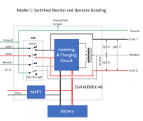
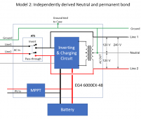
It looks like the output neutral has a permanent N-G bond or it is a dynamic N-G bond (It depends on whether the Neutral is switched). This is fine for a single inverter, but if you have more than one inverter it creates multiple N-G bonds. I wonder if there is a way to disable the N-G bond on one of the inverters.

1662847604917.png


On all inverters whit dynamic bonding, the relay's "normal" position is inverter mode so when the system is totally unhooked you should see the bond through the bonding relay.


1662847693822.png


To determine if it is an independently derived neutral, put a single 120V load on the output while in passthrough mode. If you don't see a current on the input neutral that is about the same as the load current, it is probably not an independently derived neutral.

<WARNING: RANT FOLLOWS>
Why don't these damn Chinese manufacturers document the grounding and bonding characteristics of their inverters? This is critical information that is required to create safe systems. It is nearly criminal negligence that they do not properly document what their products do.
<End rant.... I feel better now>
 
Welp, two weeks after it came out, the EG4 6000 is already on back order, not available until late October. Other than @thanhrodke, I don't know of anyone else on this forum who has one.

The 6500 is still on back order, has been since July, and won't be available until the first of October.

What do they do, order a dozen of these at a time?
I lucky enough to actually have four of the 6000 units.Two hanging on the wall, and two others that we immediately swapped another pair of 6500 orders for.
 
To determine if it is an independently derived neutral, put a single 120V load on the output while in passthrough mode. If you don't see a current on the input neutral that is about the same as the load current, it is probably not an independently derived neutral.
I'm not sure I understand about using passthrough mode. That's going to require AC in, right? I have no intention of grid use on these, so hadn't tested anything configured that way.

If I understand the test correctly, I need to hook up incoming AC power, but have batteries and solar off, and then a single 120V load connected? Then you want to see what the current is on the incoming neutral?

How could I not have current on the neutral with a single output? Are you saying that the inverter might actually be using the incoming ground as the output neutral because they are internally bonded? [and it's expecting that it's the source of all downstream power, so a bonded ground and neutral is no problem?]

In this test, do you want both incoming hots, the ground, and the neutral all connected? I will note that I ran all afternoon with the incoming ground disconnected, so the inverter could not be passing that through as the outgoing ground or neutral. But of course, I was running on solar and batteries, not passing through AC.
 
Last edited:
<WARNING: RANT FOLLOWS>
Why don't these damn Chinese manufacturers document the grounding and bonding characteristics of their inverters? This is critical information that is required to create safe systems. It is nearly criminal negligence that they do not properly document what their products do.
<End rant.... I feel better now>
Preach it. No objections from me.

BTW, nice wiring diagrams.
 
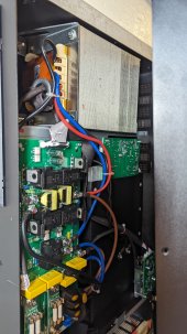
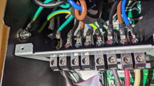
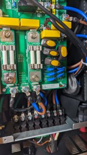
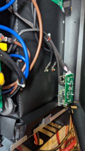
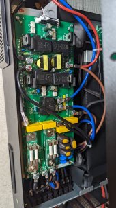
These pictures won't be provide great angles or show everything, as I can't remove the front cover without removing the security screw on the right side, but maybe if anyone is familiar enough with the electronics, they might help.

Good luck!
 

Attachments

  • PXL_20220910_210525373.jpg
    PXL_20220910_210525373.jpg
    146.2 KB · Views: 29
  • PXL_20220910_210839803.jpg
    PXL_20220910_210839803.jpg
    369.8 KB · Views: 28
  • PXL_20220910_210544186.jpg
    PXL_20220910_210544186.jpg
    146 KB · Views: 28
  • PXL_20220910_210530279.jpg
    PXL_20220910_210530279.jpg
    136.9 KB · Views: 27
  • PXL_20220910_210521117.jpg
    PXL_20220910_210521117.jpg
    153.5 KB · Views: 28
Last edited:
Back
Top