diy solar

diy solar

Solar house generator I started DIY back in 2000 - My path from Trace to Xantrex (on FLA battery) to XW Pro inverters on Tesla Model S batteries

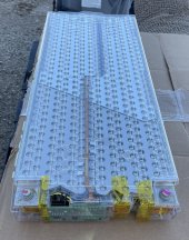
Each Tesla battery module as supplied comes with a tightly fitting top and bottom protective plastic cover. To further protect the entire face of the battery module, it's a good idea to place individual sheets of electrical grade fiberglass between each module. Some of the 5 modules I purchased yesterday did not appear to come with the insulating sheets that some ship with, if you or anyone reading your blog need a good replacement, here's a link:


0.125" x 12" x 36" electrical grade fiberglass (also called GPO3) purchased to insulate each module from each other. (McMaster Carr, part number 3345K51, at $18.48 per 12" x 36" sheet). If you need more of the orange Kapton tape, you can find it here: https://www.uline.com/BL_6407/Kapto...gclid=CPWO2_v4y9ACFZA2aQod4YMFgQ&gclsrc=aw.ds

They're even the right color.... LOL ?

PS: When buying modules, if you have the vin but are unable to get the year of the car from the seller, you can use this vin decoder: https://teslamotorsclub.com/tmc/threads/decoding-tesla-model-s-vins.7638/

DSC05281.JPG
 
Last edited:
great find, thanks

you cutting the 36" in two pieces?
You're welcome, glad to contribute to this thread, it's the best Tesla module thread on here. Yes it looks like they'll need some trimming, see attached.
 

Attachments

  • Tesla Model S Batt Dimensions.pdf
    230.6 KB · Views: 4
You hit an item that's been driving me crazy, how do we interface our JITB's to our systems, there's can and 485 but I've not seen anything about hooking it up to Schneider or Victron which is a disappointment as I run my system in Victron's DCC mode and BMS control would be nice. I'll have SOC and usage etc via the Victron shunt but that's it. :( It's the only thing missing from my system.

View attachment 128899

I did investigate what would need to be done, I came up needing a Raspberry Pi and some programming to harvest Telemetry data fro the JITB, and then needs some protocol standards for the RS485 interface, but found that hard to come by so far.

so we are stuck in that regard
 
I have 4 DC Coupled arrays. Nominal voltage is 48volt using the Conext MPPT 60 150. Using 2S 24volt panels, gives me nominal 48volts, with actual voltage being 65v to 78v incoming to the charge controllers. On one panel I have reached 60 amps sometimes, upon which the charge controllers tapers things to 60 amps maximum. Incoming wire size is 6awg. I have 3 Midnite combiner boxes on arrays 2,3 and 4 with 6 breakers circuits on each. Array #1 has a 12 breaker combiner box but will never be able to use that many these days.

These 4 arrays feed into what I call the Contactor box, where there is a relay/contactor for each of the incoming array's #6 wire. These contactors are controlled by the JITB/ESP32 Battery Management Controller box. This JITB provides a CHARGE_ENABLE control signal that is ACTIVE when the JITB determines that the battery is in a condition to be charged.

I have been spending time on correcting and updating my system's 1 line diagrams. They can be founnd on post #668 https://diysolarforum.com/threads/s...to-xantrex-to-xw-pro-inverters.11/post-678032

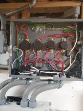
Now I am trying to document the PV Contactor box, shown here (which is just an old service panel I re-purposed):

20230112_013128.jpg

In the center are the 4 contactors, one for each array, array 1 on the left, then 2, then 3 and 4 on the right.
On the bottom are the 4 array feeds leaving the Contactor box and entering the Conext PDP to the 60amp (pre charge controller) breakers.

Incoming array lines are as follows:

Array 1 is entering the box on the center left edge
Array 2 is on the upper right edge of the box
Array 3 is on the middle right edge of the box
Array 4 is entering on the right top edge of the box.

The coils of of the contactors are driven by the RED/BLACK small leads that connect to the 12v power bus located on the lower back wall of the box, NEGATIVE on the left and POSITIVE on the right.

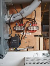
This 12v bus is energized via a 12 relay show here, outside the box on its right side, labeled "PV CONTACTOR RELAY":

20230112_013216.jpg


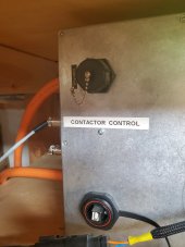
The coil for this 12v relay is connected to the JITB output control line, "CHARGE_ENABLE". The show here as CONTACTOR CONTROL:

20230112_013230.jpg

The 12v source power comes from a 12 battery in the battery bay.

The JITB checks conditions on the battery and if it determines that it is NOT SAFE to charge the battery, it will drop the CHARGE_ENABLE control line, the contactors will open and the charging will stop. This is one of the safety mechanisms of the JITB, for safe operation of the Tesla battery modules.

Future additions are 2 Dual EMPShield surge protector devices (SPDs) that will be interfaced into this Contactor Box. Each SPD will connect to 2 of the 4 arrays on the upstream side of the contactors (POS) and to the NEG connector ports and ground.
 
Last edited:
When this is all said and done, you need to put these all in a book / ebook and sell it on Amazon, it's GREAT information. Has Will commented to you yet on how much value this thread adds to the site, I sure hope so.
 
When this is all said and done, you need to put these all in a book / ebook and sell it on Amazon, it's GREAT information. Has Will commented to you yet on how much value this thread adds to the site, I sure hope so.
he did after I first posted, but given the number of posts now, I have no idea. Just glad the site is available and I can persist the info.
I do SAVE Locally now and then.

and BTW: thanks for the feedback.

Another new feature I am working on is a REMOTE ESS/BATTERY/INVERTER EMERGENCY SHUTDOWN mechanism, where firemen can press a button out by the MAIN SERVICE PANEL to have the 250amp breaker 'trip' thus disconnecting the INVERTE AC power from the house

Using the Midnite 250amp breaker (just arrived today) that accepts a 24v 'pulse' which causes the breaker to trip.
These fit exactly into the Conext PDP as a replacement breaker, just with a relay coil to connect the remote circuitry to


Here is a video by BentleyJ (also on this site)


I time indexed to the interesting part but the whole video is good

More info will come


UPDATE: 2023-03-27 After reading the manual more in depth, the XW Pro has an AUX RPO feature (remote power off). I don't need the above system. Just need a momentary button outside, run the wires to the AUX port and I have the emergency power off, remotely. RTFM, doh!
 
Last edited:
he did after I first posted, but given the number of posts now, I have no idea. Just glad the site is available and I can persist the info.
I do SAVE Locally now and then.

and BTW: thanks for the feedback.

Another new feature I am working on is a REMOTE ESS/BATTERY/INVERTER EMERGENCY SHUTDOWN mechanism, where firemen can press a button out by the MAIN SERVICE PANEL to haver the 250amp breaker 'trip' thus disconnecting the INVERTE AC power from the house

Using the Midnite 250amp breaker (just arrived today) that accepts a 24v 'pulse' which causes the breaker to trip


Here is a video by BentleyJ (also on this site)


I time indexed to the interesting part but the whole video is good

More info will come
And cutting PV, or just inverter ? Thx Re video, on dog walk, will watch when done.
 
And cutting PV, or just inverter ?
just the inverter, as my PV arrays have individual DISCONNECTS.

I don't really want to do the Rapid Shutdown method as each array needs an expensive box ($800) so I am doing a hybrid.
I have had the disconnect since each array was installed

What is new is the REMOTE ESS SHUTDOWN feature

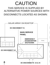
here is my HOUSE MAP.
this MAP will be attached to the service meter to provide location info for the first responders:


Thompson MAP.jpg
 
Last edited:
Handy, I use the gateway over the net and my internal network and if I was staying Sch I'd put one of these on it, I have the SCP but this is a nice add on, would look good on your system.
 
The company I just bought 5 modules from didn't show them in the ad having the M8/13mm bolt for + and - in the photo, or the rubber baby bumper covers for the bolts so I asked them to please incude those, no problem they said.... They shipped the box before the battery and it in it arrived a bunch of L brackets like is shown in the picture. I guess my modules are coming out of the X which uses the metal box on each module. Close but not quiet what I needed but glad they did because seeing this, these would make GREAT extension bars to bring the connections out and then just run copper bus bur up the front of the shelf like you have... so I'll keep them and call them next week. The 5 modules are enroute via Fedex, if they all look good and no problems I'll tell you who they are, they've been AWESOME to deal with, first one was around 700 then 4 for 3000, all including shipping.

PS: just heard from them and they’re already getting the right parts ready for me, these guys are awesome, will give you contact info once a battery has arrived and looks good.
1673739627104.png
 
Last edited:
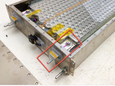
If deciding to run coolant through the modules, here are the correct fittings.

From a blog I'm reading (read update below before ordering):
The cooling loop uses a pair of 5/16" (ID) tubing nipples that appeared to a Dorman 800-080 or 800-120 type Fuel Line Quick Connector. Although these connectors were tested both bottomed out when installed and neither snapped tight as anticipated. Although one can probably install straight tubing with hose clamps, read update below for source of the correct couplings.
Details of Dorman connectors can be found here: http://www.dormanproducts.com/gsearch.aspx?type=keyword&origin=keyword&q=fuel+line+connector . These connectors can also be purchased (Dorman, ebay.com and Amazon.com) and they are available for different tubing sizes, as straight, 45 degree and 90 degree angled fittings.

Update:
It was found that Dorman 800-116 Fuel Line Connectors (Summit Racing, part RNB-800-116, at $7.97 per pair) appear to work very well. These fittings are described as 5/16" Steel to 5/16" (8 mm) Nylon Straight and the connectors snap on tightly yet can still be removed easily by pressing the tab located on the side.


DSC05324.JPG


In one of Tesla's battery patents ( http://www.google.com/patents/US20140178722 ) this fluid is described only as " water or another coolant, such as any conventional anti-freeze mixed with water, oil, or even cold air ". The blue color suggests that the fluid is Propylene glycol.

DSC05329.JPG
 
nice

one thing my fellow JITB user found is NOT to run the coolant lines in SERIES. Rather run them in PARALLEL. The resistence rises in series.

make sense?

he also found he could buy the coolant at O'Reillys
 
My 5 modules arrived today, they're freaking beautiful......... will write more and give you contact info later, all individually wrapped, all at 20 volts (a bit low) but super happy with them, ordering 3 more tomorrow so I have 12.IMG_0107.jpg
 
Just ordered the remaining goodies I hadn't gotten when I ordered the Jack in the Box....

1674533734777.png
 
yep, yep, yep

The JITB was $2999 but the parts added up. Yet for the features you NEED, the price is secondary

congrats
Thanks, I'm going to have to order a few more of those 48" extensions or custom make one to go out to the external battery bunker, I don't want anything in there but the Claymores, everything else will be in the next building.

You can't put a price on being able to sleep at night. If you want to try to tame these beasts with a $9.00 Amazon RC lipo balancer when you charge them, you're going to get the same results that Rich did when they tried it.

 
Last edited:

diy solar

diy solar
Back
Top