diy solar

diy solar

Specific grounding diagram

Grounding generally has no impact on functionality. PV, SCC, battery, inverter will all work fine regardless (unless you ground both positive and negative.)
Grounding is primarily to ensure no exposed metal has a voltage different from the earth or any metal object you might touch, like a water pipe.
And, so that if a hot wire shorts to ground, it trips a breaker and shuts off the power (won't shut off PV, but might trip GFCI.) In the case of PV, it just holds the voltage at zero forever, so ground wire is sized same as current-carrying conductors rather than oversize.

Another guy, while standing on a ladder, got a shock from his metal roof. Grounding PV array fixed that. It was apparently AC being capacitively coupled to frame.

I haven't dug into your other thread, read it a bit.

"Low battery light in inverter" - check battery voltage, see if it indicates low SoC. Check voltage at inverter battery terminals, make sure it is about the same. Try that under heavy load.
I already ran a positive and negative wire from the battery bank to the Inverter & no more low battery, it was green! Have checked the batteries over and over again and they’re good and at the right voltage. It’s just when it goes through the battery shut off switch bus bars to the inverter, the problem appears. Checked all the wires, fuses, and replace the battery switch – no luck!
Checked the voltage through each connection point & it’s good.
The only thing I can think of is the shunt, and that looks good from the readings on VictronConnect app.
 

Attachments

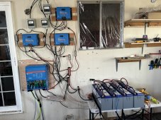
  • 61F76ACA-58E5-4D5F-BB0E-07CC6B335E48.jpeg
    61F76ACA-58E5-4D5F-BB0E-07CC6B335E48.jpeg
    355.1 KB · Views: 4
I already ran a positive and negative wire from the battery bank to the Inverter & no more low battery, it was green! Have checked the batteries over and over again and they’re good and at the right voltage. It’s just when it goes through the battery shut off switch bus bars to the inverter, the problem appears. Checked all the wires, fuses, and replace the battery switch – no luck!
Checked the voltage through each connection point & it’s good.
The only thing I can think of is the shunt, and that looks good from the readings on VictronConnect app.
I think you have isolated the problem to between inverter.negative and battery.negative.
You should be able to bisect from there.
 
I think you have isolated the problem to between inverter.negative and battery.negative.
You should be able to bisect from there.
I’m going to try to take off the shunt and see if that makes a difference, hopefully I won’t damage anything as I’m leaving the solar panels shut down.
 
I’m going to try to take off the shunt and see if that makes a difference, hopefully I won’t damage anything as I’m leaving the solar panels shut down.
Have you tried bypassing the big aluminum dingus?
If you do, you will likely have to pre-charge the mutiplus capacitors with a resistor.
 
Have you tried bypassing the big aluminum dingus?
If you do, you will likely have to pre-charge the mutiplus capacitors with a resistor.
I believe that’s only going to be a problem if there’s a load on the system, there will be no loads whatsoever.
I did run the positive wire from the batteries alone to the inverter positive and the negative wire to the negative on the CSL aluminum dingus! I got a green light and no voltage disconnect.
That’s why I say it’s definitely a gremlin I can’t discover! ?
If the inverter caps dissipate their charge they will pull serious current, no load required.
 
If the inverter caps dissipate their charge they will pull serious current, no load required.
I’m not sure how to get to the capacitors to discharge them, they seem to be buried deep into the inverter?
 
Do you have a test case to reproduce the issue 100% of the time?
 
Do you have a test case to reproduce the issue 100% of the time?
Yes! If you mean for the battery, shut down, happens every time I put the fuse into the positive connection on the inverter. I turn the battery switch on and within two seconds everything shuts down.
I left the inverter on to see what would happen when I turn the power on, it reads red low voltage battery? Doesn’t make any sense as there’s plenty of juice in the battery as it’s at a 100%.
Since you have a 100% reproducible baseline.
If the problem really is between inverter negative and battery negative you should be able to find it by bisection.
If my eyes don't decieve me there is only shunt, negative busbar and dingus.
 
Since you have a 100% reproducible baseline.
If the problem really is between inverter negative and battery negative you should be able to find it by bisection.
If my eyes don't decieve me there is only shunt, negative busbar and dingus.
Yep, if this is what you mean by bisection or three connections? That’s why I thought I might remove the shunt and see if that changes anything.
 
Yep, if this is what you mean by bisection or three? That’s why I thought I might remove the shunt and see if that changes anything.
First test is connect the battery negative directly to inverter negative.
We expect that test to pass.
 
First test is connect the battery negative directly to inverter negative.
We expect that test to pass.
It did, I already did that. I guess it would be a waste of time to remove the shunt then.?
 
It did, I already did that. ?
Next test is to connect inverter.negative to the load side of the shunt bypassing the CLS and negative busbar.
See if that reproduces the problem or not.
 
Next test is to connect inverter.negative to the load side of the shunt bypassing the CLS and negative busbar.
See if that reproduces the problem or not.
Should I take it from the inverter negative to the busbar negative? I can still bypass the CSL.
I’ll have to try that tomorrow, wiped out from spending most of the day with this problem. It’s close to my bedtime. ?
 
Should I take it from the inverter negative to the busbar negative? I can still bypass the CSL.
I’ll have to try that tomorrow, wiped out from spending most of the day with this problem. It’s close to my bedtime. ?
Lets pick it up tomorrow when you are fresh.
 
Let’s pick it up tomorrow when you are fresh.
Just remembered, it couldn’t be the CSL, as I had hooked up the negative wire from the battery neg to the CSL negative and the inverter showed a green light! I had also taken positive from the battery bank to the positive of the inverter in one long wire. bypassing both the battery switch and the busbars.
This is what battleborn had asked me to do and it worked without any problems!
I have already replaced the battery switch and that works now.
 
Direct wires works, through many things causes "low battery" signal?
Measure voltage at battery, then at inverter. Is it lower? (under load)
Under steady current (some level that doesn't trigger the disconnect), use DMM to check voltage across each connection.
You may find a high resistance connection.

That should be faster than repeatedly reconfiguring with different things removed.
That would be nice, but you can’t test something that won’t turn on? The battery shut down after two seconds before I can take any readings.
 
Back
Top