42OhmsPA
What's in a title?
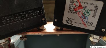
Interesting. Be sure to post pictures when you receive it. I hope it works out.its the ASF48100U200-H but made by a company called JHOTA.


Interesting. Be sure to post pictures when you receive it. I hope it works out.its the ASF48100U200-H but made by a company called JHOTA.
Thanks for all your help and the kind words. I'll be sure to let you know how it goesInteresting. Be sure to post pictures when you receive it. I hope it works out.
 nassaunationalcable.com
 nassaunationalcable.com
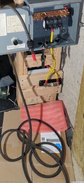
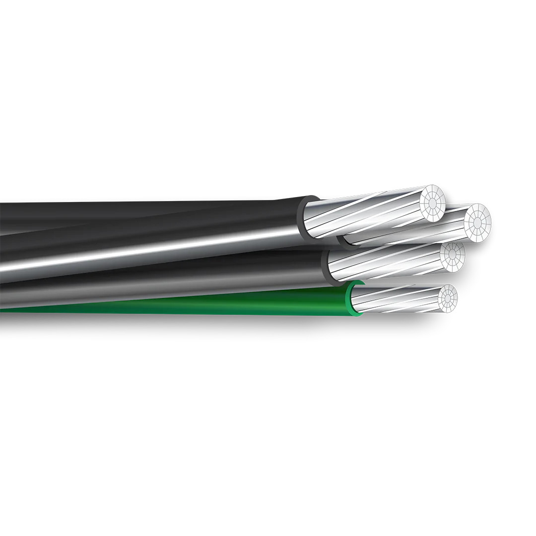
I don't think there is any chance 3awg will fit. I'd double check the manual.So I am getting the stuff I need to hook this beast up, the manual states 3awg for the AC in and out (I'm running 120 only) would this cable work from the AC out to the breaker panel and from the generator to the inverter?
2-2-2-4 Aluminum Mobile Home Feeder Cable
Specifications : Cable Construction : 2-2-2-4, Phase Conductor; Insulation (mils) : 60, Insul. Phase Conductor; Diameter (inches) : 0.390, Insul. Grounded (Neutral) Conductor; Diameter Inches : 0.390, Insul. Equipment Grounding Conductor; Diameter Inches : 0.290, Cable Diameter Inches : 0.944...
Or
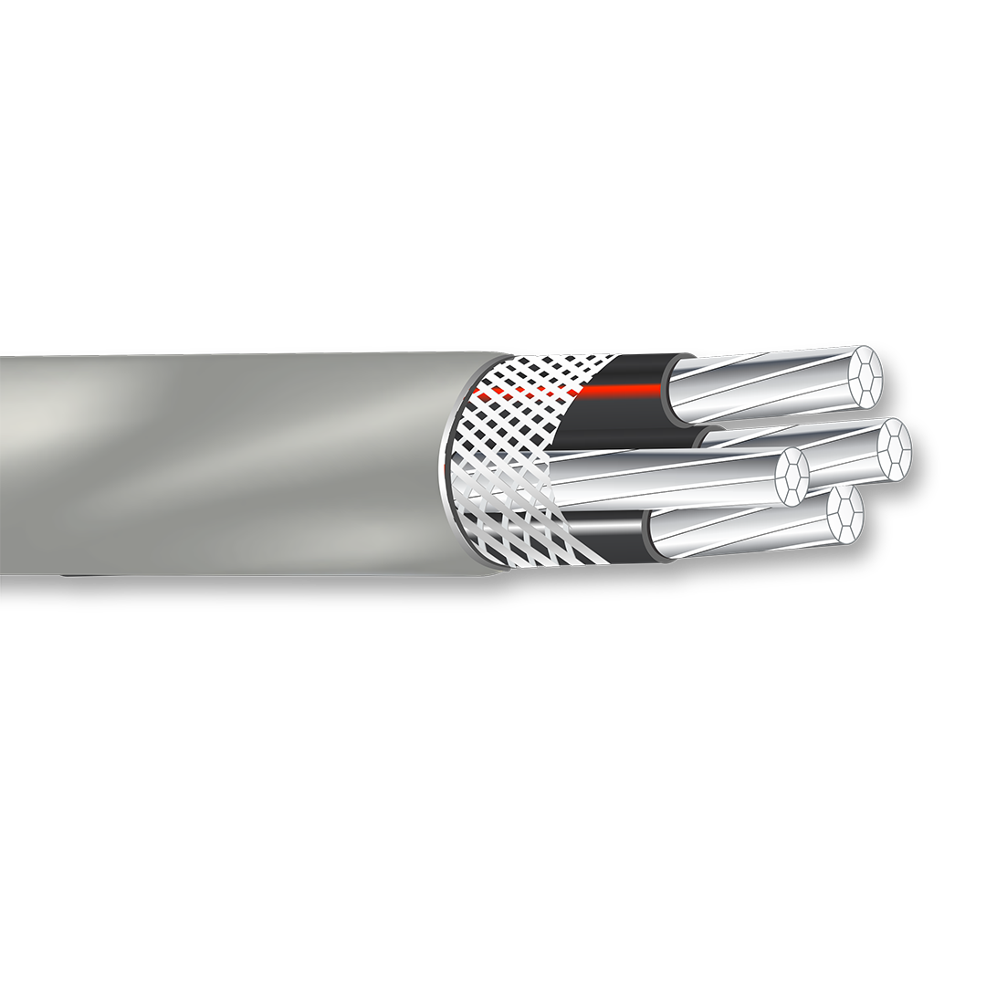
2-2-2-4 ALUMINUM SER CABLE
Specifications : Insulated Cond(s) Size AWG : 2, Bare Conductor Size AWG : 4, Nominal O.D. Inches : 0.863, Approx. Weight lb/1000FT : 346 lbs, Ampacity at 90°C : 100 Amps, Ampacity in dwelling : 100 Amps. Standards : 90°C wet or dry locations, Ampacities based on National Electric Code, 2005...

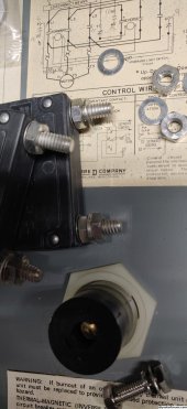
My guess your correct, because the manual recommends the use of ferrule ends which crimps on 3awg wire but the end is less in diameter, because it's solid metal, but even so I don't understand them recommending 6 and 3 awg wire when the wire from the same terminal to the inner workings of the inverter are 10awg, lol wtf ;P anyways what are you using for each N L1 and L2?I really don't think 3awg will fit in any of them and 4 would be tight. I hope the manual is correct and I'm wrong.
Yea, I didn't understand that either.My guess your correct, because the manual recommends the use of ferrule ends which crimps on 3awg wire but the end is less in diameter, because it's solid metal, but even so I don't understand them recommending 6 and 3 awg wire when the wire from the same terminal to the inner workings of the inverter are 10awg, lol wtf ;P
6AWG THHN.anyways what are you using for each N L1 and L2?

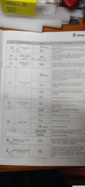
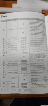
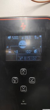
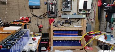
How's this? (attached). Display screen bottom right is software version. Let me know if you can't read any of my chicken scratch and I'll try to decipher.Hi, can you post your settings on the inverter...
How's this? (attached). Display screen bottom right is software version. Let me know if you can't read any of my chicken scratch
I think you covered the n/g option. have you ever investigated your current on ground issue? Thanks for posting the settings. seems pretty straightforward. Just curious, what are your battery and pv kw?Updates.
I haven't forgotten about the N/G bond tests and other items mentioned a page or so ago. Work life and life hasn't let me take the house loads offline to test yet.
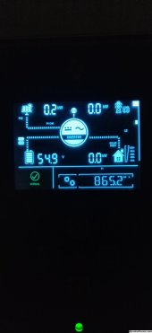
I'm slowly closing in on 1Mw with 0 issues.
I figured out what the root cause was of the random restarts a few weeks / pages ago... When some brilliant person was setting up the BMS's way back when they set max charge current at 60a per pack... I realized this while I was programming the 3rd BMS. They have since been changed to 110a, just under 0.5c, and I've had no issues since.... User error strikes again...
I never did clamp the ground or figure that out. Thanks for the reminder.I think you covered the n/g option. have you ever investigated your current on ground issue? Thanks for posting the settings. seems pretty straightforward. Just curious, what are your battery and pv kw?
Never thought of that with V2L. You could limit the Victron AC in to 15a and pull rest from DC (PV and Battery), power assist function or whatever.Is this inverter capable of generator boost like a Victron? Want to operate it in parallel with either my generator or my car’s V2L.
Ideally with surplus power going to charge and the inverter automatically making up the demand above the power source’s limit.
I don't believe so. There are settings for maximum grid/generator charging current and a few different time schedule options as well as overload bypass.Is this inverter capable of generator boost like a Victron? Want to operate it in parallel with either my generator or my car’s V2L.
Ideally with surplus power going to charge and the inverter automatically making up the demand above the power source’s limit.