diy solar

diy solar

SSR testing

Note: If anyone is interested, I added a theory of operation to the relay circuit above. It is also copied here:

1588463442668.png

Turn On sequence
  1. The circuit as shown is the starting point with everything off.
    Note that in this state, both sides of relay 2 coil are hooked to the positive, so nothing will happen.
  2. The Chargery energizes the signal, causing relay 1 to turn on, connecting pin 1 of the coil of relay 2 to negative.
  3. Since pin 2 of the coil of Relay 2 is already connected to positive, the coil is energized in a 'positive' direction, energizing the load and flipping the auxiliary contact to B(negative).
  4. When auxilary contact on relay 2 flipped to negative, both sides of the coil of relay 2 is connected to negative and the coil is de-energized. However, since relay 2 is a bi-stable relay, it does not change state.
At this point relay 2 is on but not drawing any current on the coil. Relay 1 is on but only drawing about 20mA.

Turn off sequence
  1. The initial condition is that relay 1 is on and the bi-stable relay is on but the coil is not energized because both sides of the relay 2 coil are connected to negative.
  2. The Chargery turns off the relay signal so relay 1 switches state, connecting the pin 1 of the coil of relay 2 to positive.
  3. Relay two now has an 'Negative' energized coil with Positive on Pin 1 and Negative on Pin 2. This causes the relay to de-energize the load and flipping the auxiliary contact to “A” (Positive).
  4. Both sides of the relay 2 coil are now connected to Positive so the coil is de-energized but since it is a bi-stable relay, it does not change state.
Note, the opposing diodes across the coil of relay 2 are there to drain the voltage spike that will occur when the coil is de-energized.
 
Well I think we may have a winner!

Tested this

View attachment 9352


After 15 minutes at 50 Amps Temperature was only 71 Degrees F. Voltage drop was 0.1 V and Controll load draw at 12Volts was 0.34 Amp

This 240 Amp relay will be about $40.00 including the beefy heat sink ($6.00)
The 500 Amp relay I will test Tomorrow but It is quite a bit more expensive $100 including heat Sink. It has max voltage of 75Volts

I do not have a spec sheet as this is what distributor recommended and sent me to try.

Got any of these 240 amp or 500 amp in stock for paypal purchase (May 4, 2020 post) , or web links / info. on Relays on your radar, yet to be tested ? ... I read reast of thread next ...
 
Got any of these 240 amp or 500 amp in stock for paypal purchase (May 4, 2020 post) , or web links / info. on Relays on your radar, yet to be tested ? ... I read reast of thread next ...
Those only have a small screw and there is no way to attach battery cables with big lugs to them. I got two from Craig to test and couldn't because of that, so they are boxed and going back to Craig. The company made NEW SSR Relays @ 500A & 1000A with Big Lugs and pads, the first versions are en-route to Craig & Myself for test & Evaluation.

My Dongya Relay's arrived today with instructions, specs sheets and even instructions (first time I ever saw that !) but these are NOT SSR's, they are canister type BUT it seems they sent me the wrong pair (ruckus-stuckus-frickus-fruckus, ala Fred Flinstone) could have a BamBam moment as time is running for me to do anymore.. as in by the end of this week because Life (thanks to spring) must take over and no time to furtle around with this stuff.

IF you are Curious:

Big Lug 500A SSR : https://www.alibaba.com/product-detail/DC-control-DC-solid-state-relay_62549649837.html?spm=a2747.manage.0.0.3d1571d2AmThhr&bypass=true

Big Lug 1000A SSR : https://www.alibaba.com/product-detail/DC-control-DC-solid-state-relay_62549285366.html?spm=a2700.icbuShop.41413.11.72317242imd258&fullFirstScreen=true&bypass=true

Dongya Energy Saver Contactor Relays, similar to Gigavac & TE: https://www.dc-contactors.com/dh150-300-high-voltage-dc-contactor/high-voltage-dc-contactor-dh200h
 
Wow. Very Interesting Topic with 8 * 280 Ah LiFePO4s on way, and a Chargery BMS8T in hand. After Will's recent video clips on that Chargery BMS; with highlight on temp generated and watts used by those relay, I am all eyes n ears on what is new with relay options. I would highly value seeing a low watt use relay that could handle 24vdc or 48vdc with 250 amps. with longevity potential. ;+)

If I wanted to half my max amp for a relay needs on my using two LV2424 All In One Units on one set of 24v LiFePO4s for a 240v ac split phase ... I think I could put one relay on each battery cable of each All in One Unit. Does that sound doable for one of these relay hooked up to a Chargery BMS8T? I could imagine two SSR type relays could be wired from BMS in parallel or in series, but parrallel would likely be safer. Does that sound like ok ideas. ? ??

I am thinking of this if for Back Up / to disconnect All In One units from Battery if battery most from too low of voltage on one cell danger/ ... but aslo if an overheat temp at battery was detected. I think the All in one would would right to manage max charge volts, and minimum battery volts, ... but not really one 3.2 v cell getting too low of volts.

I am retiring consideration of Will low cost way of wiring SSR Occicoupler Relay to Turn Off the Inverter in his All in One, while wiring All in One directly to battery bank (not relay on battery wire) ; as I register my LV2424 All In Ones do not have a separate inverter switch (that I know about after manual study/ wonder if there still might be a way that does not void warranty support). There is one on/off switch that off would turn off everything including MPP solar charging to battery (not what I would want)

Looking for more info. on full amp test/ surge or otherwise, on the SSR (solid state relay) options, as my Xuba battery order is still in shipping route mode. Got this topic on my research list. Thanks Craig and thread members for helping me learn more all the time.
 
Those only have a small screw and there is no way to attach battery cables with big lugs to them. I got two from Craig to test and couldn't because of that, so they are boxed and going back to Craig. The company made NEW SSR Relays @ 500A & 1000A with Big Lugs and pads, the first versions are en-route to Craig & Myself for test & Evaluation.

My Dongya Relay's arrived today with instructions, specs sheets and even instructions (first time I ever saw that !) but these are NOT SSR's, they are canister type BUT it seems they sent me the wrong pair (ruckus-stuckus-frickus-fruckus, ala Fred Flinstone) could have a BamBam moment as time is running for me to do anymore.. as in by the end of this week because Life (thanks to spring) must take over and no time to furtle around with this stuff.

IF you are Curious:

Big Lug 500A SSR : https://www.alibaba.com/product-detail/DC-control-DC-solid-state-relay_62549649837.html?spm=a2747.manage.0.0.3d1571d2AmThhr&bypass=true

Big Lug 1000A SSR : https://www.alibaba.com/product-detail/DC-control-DC-solid-state-relay_62549285366.html?spm=a2700.icbuShop.41413.11.72317242imd258&fullFirstScreen=true&bypass=true

Dongya Energy Saver Contactor Relays, similar to Gigavac & TE: https://www.dc-contactors.com/dh150-300-high-voltage-dc-contactor/high-voltage-dc-contactor-dh200h
Thank You Steve S ... Awesome info. / ... and line up for testing. Looking up the SSR relay info. and reading specs/ description; I noticed: "Precautions: 1. Must add suppression circuit for inductive load. ..." I wonder what that is about. Looking forward to test results and learning more.
 
Last edited:
I noticed: "Precautions: 1. Must add suppression circuit for inductive load. ..." I wonder what that is about.

On an inductive load, when you turn off the current there can be a very large voltage spike back from the load. This spike can damage the silicon in the SSR.

I don't think an inverter presents as an inductive load, but I am not sure.

Here is an article that talks about a few ways of doing the suppression.... I would lean toward the Zenor diode for this purpose.

https://www.electronics-tutorials.ws/power/transient-suppression.html
 
Gee Wiz, Today felt like Christmas in the midst of a disappointment but xmas wins ! ?
The 500A SSR's arrived, as well as the pair of Dongya DH200's, couple of quick photo's to ponder upon, sorry Craig, but like I was excited to get them I think some folks are keen to see what they can too at this point. ? Links to these relays are 4 posts above.

I've received these in pairs. my plan is that I'll install then in place with the two 280AH packs that I'm just finishing up with. I'll see how it goes from there and have a separate post on that with a link to here as I don't think my testing will be like Craig's or others, dunno... we'll see. Unfortunately now that spring has fully sprung I have other urgent priorities.

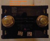
500A top view 1/2" studs
500A-SSR face.jpg


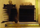
500A Side View

500A-SSR profile.jpg


The Dongya DH200H contactor next to a MZJ-200A which came from Chargery.
DH200H-vs-MZJ-200A.jpg
 
Last edited:
Gee Wiz, Today felt like Christmas in the midst of a disappointment but xmas wins ! ?
The 500A SSR's arrived, as well as the pair of Dongya DH200's, couple of quick photo's to ponder upon, sorry Craig, but like I was excited to get them I think some folks are keen to see what they can too at this point. ? Links to these relays are 4 posts above.

I've received these in pairs. my plan is that I'll install then in place with the two 280AH packs that I'm just finishing up with. I'll see how it goes from there and have a separate post on that with a link to here as I don't think my testing will be like Craig's or others, dunno... we'll see. Unfortunately now that spring has fully sprung I have other urgent priorities.

500A top view 1/2" studs
View attachment 12566


500A Side View

View attachment 12567


The Dongya DH200H contactor next to a MZJ-200A which came from Chargery.
View attachment 12568
Those are Huuugggeeee I tell you.

I'm supposed to have mine today as well but I'm in Idaho so I won't get to test til Wednesday or Thursday.
 
Those are Huuugggeeee I tell you.

I'm supposed to have mine today as well but I'm in Idaho so I won't get to test til Wednesday or Thursday.
To be perfectly honest, they surprised me with the size, the relay's themselves are 4"x3"x1" thick... freakin Monsters ! Gonna have to drill the lugs out to 1/2" for these beasts. I have a serious suspicion that they won't get very warm in my use.... I average between 6-10A draw off the batteries, when the well pump kicks on maybe 55A, microwave & coffee maker are the next two heavies which is still not huge... I've seen my system hit 160A Draw for very short periods, so for 500A SSR's they should not break a sweat at all... but they can adequately handle the max draw potential of the inverter (12kw max surge).

Bugger to slow me down though... I just fried a BMS8T when removing the ShunBin nightmare, shorted a relay contact and it cooked up and made stinky magic smoke...
Yes always unplug the relay control before working on it. Jason can send you a box without the display and shunt.
 
To be perfectly honest, they surprised me with the size, the relay's themselves are 4"x3"x1" thick... freakin Monsters ! Gonna have to drill the lugs out to 1/2" for these beasts. I have a serious suspicion that they won't get very warm in my use.... I average between 6-10A draw off the batteries, when the well pump kicks on maybe 55A, microwave & coffee maker are the next two heavies which is still not huge... I've seen my system hit 160A Draw for very short periods, so for 500A SSR's they should not break a sweat at all... but they can adequately handle the max draw potential of the inverter (12kw max surge).

Bugger to slow me down though... I just fried a BMS8T when removing the ShunBin nightmare, shorted a relay contact and it cooked up and made stinky magic smoke...
Sorry to hear about your fried BMS8T experience from removing the ShunBin nightmare. I think ShunBin is the name of the orange relay supplier by Chargery ? To register this heads up lesson for anyone reading about it; Was that from letting the two wires to relay coil breifly touch each other? What could you have done differently to ptotect the BMS8T? / ...on other note: That 500A SSR looks like a winner, and I hope it is. I wonder how many amps it can really handle. :+)
 
Sorry to hear about your fried BMS8T experience from removing the ShunBin nightmare. I think ShunBin is the name of the orange relay supplier by Chargery ? To register this heads up lesson for anyone reading about it; Was that from letting the two wires to relay coil breifly touch each other? What could you have done differently to ptotect the BMS8T? / ...on other note: That 500A SSR looks like a winner, and I hope it is. I wonder how many amps it can really handle. :+)
The ShunBin is a pre-assembled (24V/400AH) battery pack I bought in November an turned out to be a pile of BLEEP... link on it is in my signature, total ripoff scam that cost me 4 grand USD. Several companies make relays like Chargery offers, they are pretty common and have many variations. I do believe that Jason will have other relays on offer as well, soon enough because the expanding use cases such as solar storage warrant having such offerings being available.

As for frying the BMS control module, Jason is already shipping me a new control module to replace it. It was MY BAD... I was disconnecting the (+) lead from the battery on the first relay and I dropped teh nut which made contact between the battery + and the 12V contact lead to the relay which fried the actuator circuit in the BMS. I should have and could have disconnected ANY OTHER battery + lead and it would not have occurred. momentary brain fart = wasted $$$.
 
This is slight side track, but related:

Last night, I took in Will's Build with Victron Smart BatteryProtect - 220AMP - 6-35 VDC ( a second time/ flipping through Youtube options).

I appreciated the lesson about charging up capaictors in equipment before hooking up main battery cables. That Victron Smart BatteryProtect kind of looks like another SSR Relay option, while some Amazon Q & As claims said it could be destroyed by an inverter or by running both draw and charge direction currents through it (not sure why, or if that is correct info.).

Trying to figure out how to best use a SSR Relay with a Chargery BMS8T for my LV2424 All In (s) to protect a 24v * 280 Ah LiFePO4 set: While that clip shows Will wiring that Battery Protect unit between just the Battery and Inverter draw; I registered Will saying disconnecting a MPPT solar charger from a battery circuit while charging could possible damage MPPT solar charger equipment. In considering my particular relay options for a LV2424 All In One (MPP brand name) that has only one set of battery cables to and from the battery for both solar charging in and inverter draw out, plus the limitation of only one off & on switch for the whole unit/ and no separate inverter switch (like that other series All In One unit Will wire an OcciCoupler SSR relay to for turning off the Inverter; ... This New Idea popped up for me:

Why not turn off my Inverter by turning off the 25 Amp AC Out with an AC Relay between my All In One output to the AC out Circuit Breaker Box I will be connecting to. That would accomplish the same as turning off the Inverter unless their was some oddball extreme inverter malfunction.

My thinking is: The BMS is a back up battery protector; proper configuration within my All In One is my main battery protector; my biggest battery danger is letting one cell get too low; I am not concerned about charging in a freeze where I live, especially while storing batteries inside an insulated building; and while I would also like to turn off solar charging when any battery was too hot, that might not be a concern.

If anyone has any pros or cons type feedback, or a better thread suggestion for me; I am in study mode. Thanks in Advance ;+)
 
Last edited:
The ShunBin is a pre-assembled (24V/400AH) battery pack I bought in November an turned out to be a pile of BLEEP... link on it is in my signature, total ripoff scam that cost me 4 grand USD. Several companies make relays like Chargery offers, they are pretty common and have many variations. I do believe that Jason will have other relays on offer as well, soon enough because the expanding use cases such as solar storage warrant having such offerings being available.

As for frying the BMS control module, Jason is already shipping me a new control module to replace it. It was MY BAD... I was disconnecting the (+) lead from the battery on the first relay and I dropped teh nut which made contact between the battery + and the 12V contact lead to the relay which fried the actuator circuit in the BMS. I should have and could have disconnected ANY OTHER battery + lead and it would not have occurred. momentary brain fart = wasted $$$.
Live n Learn: Some Lessons are harder than others. Thanks for sharing your specifics. I would rather learn from your shared learning curves, but know I will also be learning from more of my own mistakes. If we never make mistakes, we are being like a sheep and not taking enough risks (or thinking like a narcissist that is stuck in blame mode). Appreciating this forum ;+)
 
This is slight side track, but related:

Last night, I took in Will's Build with Victron Smart BatteryProtect - 220AMP - 6-35 VDC ( a second time/ flipping through Youtube options).

I appreciated the lesson about charging up capaictors in equipment before hooking up main battery cables. That Victron Smart BatteryProtect kind of looks like another SSR Relay option, while some Amazon Q & As claims said it could be destroyed by an inverter or by running both draw and charge direction currents through it (not sure why, or if that is correct info.).

Trying to figure out how to best use a SSR Relay with a Chargery BMS8T for my LV2424 All In (s) to protect a 24v * 280 Ah LiFePO4 set: While that clip shows Will wiring that Battery Protect unit between just the Battery and Inverter draw; I registered Will saying disconnecting a MPPT solar charger from a battery circuit while charging could possible damage MPPT solar charger equipment. In considering my particular relay options for a LV2424 All In One (MPP brand name) that has only one set of battery cables to and from the battery for both solar charging in and inverter draw out, plus the limitation of only one off & on switch for the whole unit/ and no separate inverter switch (like that other series All In One unit Will wire an OcciCoupler SSR relay to for turning off the Inverter; ... This New Idea popped up for me:

Why not turn off my Inverter by turning off the 25 Amp AC Out with an AC Relay between my All In One output to the AC out Circuit Breaker Box I will be connecting to. That would accomplish the same as turning off the Inverter unless their was some oddball extreme inverter malfunction.

My thinking is: The BMS is a back up battery protector; proper configuration within my All In One is my main battery protector; my biggest battery danger is letting one cell get too low; I am not concerned about charging in a freeze where I live, especially while storing batteries inside an insulated building; and while I would also like to turn off solar charging when any battery was too hot, that might not be a concern.

If anyone has any pros or cons type feedback, or a better thread suggestion for me; I am in study mode. Thanks in Advance ;+)
Shutting off the AC draw us another option. After I test the new SSR I want to make a post on the various ways to use Chargery and interface with SCC and inverters.
 
This is a DIT crowd, just throwing it out there...

Build your own high side switch. Might not be that difficult.
https://electronics.stackexchange.com/questions/353218/p-channel-mosfet-switch

Need a p-channel mosfet. STP780PF55 could be a candidate. 80A, 18 mohm
https://www.ebay.com/itm/10pcs-STP80PF55-TO-220/302720043425?hash=item467b8549a1:g:--QAAOSwtuBa-FY4

Perhaps parallel 10 mosfets to get 200A switching capability. That would be 20A per mosfet & 7W power dissipation per mosfet. Requires a heat sink.
https://electronics.stackexchange.com/questions/274557/parallel-mosfets
 
Shutting off the AC draw us another option. After I test the new SSR I want to make a post on the various ways to use Chargery and interface with SCC and inverters.
Craig. I bet you would know off top of your head: Does the Chargery BMS8T have the ability to work with a NC (normally Closed) Relay where current to coil turns the switch contact OFF) - OR - a NO (normally Open) Relay when coil current turns on/ & keeps contact switch ON. ??? I bet I could find spec for relay voltage, but doubt I could easily find info. on NO or NC Relay question! Sounds like you think Shutting off the AC draw for my All In One hookup maybe a good option for me? I am thankful for your relay testing and sharing. I think this thread, and forum is an awesome learning center.
 
So far the best combination I've found for a Chargery relay setup is these two gismos. Everything you need to run one contactor for common port (by wiring the relay controller NO contacts in series to one relay) or two contactors. Plus you get an extra controller for cooling fans or whatever. Lowest operating current and the coolest running of everything I have tested. Probably my final setup.


I bought two of the contactors and they looked new.

I wired the Chargery relay wires to the high triggers and common and brought 12 v in from my stepdown to power the controller and the contactor coil.
 
@onemorebattery do you possibly have any photos or schematics of this setup? If one didn’t have a 12v step down, is there another way? Thank you!
 
@onemorebattery do you possibly have any photos or schematics of this setup? If one didn’t have a 12v step down, is there another way? Thank you!

I guess I could cobble together a schematic. Here's the stepdown that I use.


Edit: Diagram for common port single relay

chargerycontactorsetup.png

For two contactors run 12v+ through NO1/COM1 and NO2/COM2 separately to each coil+.

The parts:


Last edited:
I guess I could cobble together a schematic. Here's the stepdown that I use.


Edit: Diagram for common port single relay

View attachment 12677

For two contactors run 12v+ through NO1/COM1 and NO2/COM2 separately to each coil+.

The parts:


@onemorebattery - I believe the TE Contactor that you identified is also used by the REC bms system, a quality product.
Do you have yours setup as a common port, single contactor today?

Btw - nice setup, seems like a winner. Wouldn’t mind a picture to get an idea on you enclosure if your using one.
Thanks
 

diy solar

diy solar
Back
Top