diy solar

diy solar

Subpanel is 99% 120V except by Dryer that is 240V. Is it still okay to connect the Inverter AC-OUT 120V into both L1/L2 ?

Usually it's a 3 wire romex. Black, red,white, and bare.
Black and red are circuits on L1 and L2, white wire is the neutral for both. (Shared neutral)
Since you will be combining L1 and L2, a multi-wire branch circuit neutral would have to carry twice the current.
@timselectric Got it. Yes, it makes sense. Today as the sub-panel is fed by the main using a 240v split phase, the neutral wire in a give moment will carry current from just one of the hot wires, or L1 or L2. Does it make sense ? But once I combine L1/L2 it can have to carry current from both wires at the same moment. But in that case it will be limited to the max current that my inverter can delivery, right ? Make sense ?
So as long the inverter AC output is < than the neutral wire rate I will be good and what means that I must use a right breaker for the solar system AC output.
Am I at least going/thinking in the right direction or Am I totally lost ? :ROFLMAO:
Yup
You've got it.
 
@timselectric
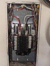
as promised, here is my sub-panel inside. It looks like the only wires coming from the main panel is the L1, L2, N and Ground. And again the breaker to disable the sub-panel is in the main panel but the original idea is to add one top main breaker (using the same 80amps that we have in the main panel) and add a 2 pole breaker on the top left + interlock, so that way I would be able to turn on/off (switch) the current coming from the main pain or inverter.
PXL_20230503_141653844.jpg

Btw, I installed an Emporia 2 Vue with 16 sensors. Tried to organize it the best way to leave wires not in from of any break, so it is +- okay.
But that thing is amazing. How now I can see all my usages in that sub-panel. I would love to install it as well for my heat pump and furnace but as both breakers are in the main panel I dont want to mess with it for now.

And on my researches/studies I saw that I will need permits in order to install a solar system in my house. So Im looking for some company that can help with the design and also have a signed engineering plans. Lets see.....
 
In addition to the good advice above - get a 120v dryer (heat-pump model) and wire a different plug and then you're 100% 120v both panel and operationally within you're home :)
 
No Hazzard.
It just won't work on 120v.

I think it will work, just no heat.
Motor and controls get 120V and operate as before.

If this is 120V backup for a house that normally gets 120/240V, would be a reasonable thing to do.

If you want it to work on 120V, could rewire dryer for 120V. Either keep existing 30A 120/240V plug or change to 120V plug.

For maximum WAF (wife acceptance factor) with 120V backup, add a switch or relay to the dryer so heating element switches between 120V and 240V.

Usually it's a 3 wire romex. Black, red,white, and bare.
Black and red are circuits on L1 and L2, white wire is the neutral for both. (Shared neutral)
Since you will be combining L1 and L2, a multi-wire branch circuit neutral would have to carry twice the current.

If there had been a MWBC, could be fixed by connecting red and black both to the same 20A breaker. Then white isn't asked to carry more than 20A, no problem.
 
I think it will work, just no heat.
Motor and controls get 120V and operate as before.

If this is 120V backup for a house that normally gets 120/240V, would be a reasonable thing to do.

If you want it to work on 120V, could rewire dryer for 120V. Either keep existing 30A 120/240V plug or change to 120V plug.

For maximum WAF (wife acceptance factor) with 120V backup, add a switch or relay to the dryer so heating element switches between 120V and 240V.
The dryer outlet is not even being used.
They have a gas dryer.
If there had been a MWBC, could be fixed by connecting red and black both to the same 20A breaker. Then white isn't asked to carry more than 20A, no problem.
Correct
 
Thank you everyone... you guys are experts.
So, for now have 2 homeworkes:
  1. Learn my usage on the sub-panel so I can know exactly what Im using and have a good idea what would be best size of my solar system
  2. Learn more about permits that I will need :-( that will be probably the bore part and hope I can find a company that will work with me to get everything 100% legal
Thank one more time everyone
 
Last edited:
Perfect! Get yourself one of these:


61amKmEgcDL._AC_SL1500_.jpg


:devilish:
 
@usphisics On your emporia go to menu/notifications/ add alert. There add an alert for mains consumption of slightly lower than the rated surge of the inverter your looking at for 3 sec. (Or rated constant for 30sec)
It will send you an alert if that sub panel exceeds the surge (constant) watts of the inverter
Thank you…. I just created one alert. But that is nice to be able to see 18 breakers/appliances usage.
Most part of the time the load is less than 500wh but once wife and kids get home they start to turn on stuffs on and then it goes closer to 1kWh.
So far the biggest load are microwave, kettle, air fryer and suffs like that. That is when I can have peaks over 2kWh.
So far per day it is between 10kWh and 12kWh. Weekend probably will be more, lets see….
But it is really nice to be able to see where and understand my loads, so it will for sure change my mind set about the size of my future system.
 
I didn't see this mentioned in the thread, but, If you are connecting one leg to both sides of the bus, doesn't that mean you are loading up one circuit of your 240V 2 phase inverter? If this does not apply, let me know and I will delete this comment.
It's a single phase 120v inverter.
 
I don't see any multi-wire branch circuits. So, you are good to go.
@timselectric sorry to bother you again but I was reading about the MWBC and I think I got the basic concept about it and as you said before it looks like that I don't have it between my sub panel and the house BUT going back and looking between the main-panel and the sub-panel, would not that be the case? I mean that is a MWBC, right? L1 and L2 sharing the Neutral wire..... So having that in mind (if Im right) I keep thinking what would be the current flow if I set up the system as I was thinking....
  • Turn off the break that connects the main and sub panels, so L1/L2 between them would not have current but Neutral would stay connected/shared between them all the time, right ?
  • Now on sub-panel I have a source of power ON. Like my solar system. And as the original ideal was, I connect my 120V wire into both L1 and L2 so I can have current in both side of my sub-panel, it would be 120V single phase as we already discuss about it (again not split phase).
  • Now I go home and turn on something, like TV or light, whatever. The current flow would comes from the source to power what ever it needs and comes back to the source via neutral wire, right ?
So the last step is where I have questions...... Will the current travels back to the source JUST USING neutral wire/bus bar from the sub-panel OR it would somehow travel to the main-panel for some reason. Sorry, again super newbie/ignorant person here :cry:
On my heat I have that the current would do the shortest path back to the source, so it would not have current flowing back to the main-panel at all even it and sub-panel still having a shared neutral BUT again, just to be safe I prefer to ask/bother you, sorry... LOL
It won't travel to the main panel.
Shortest path is correct.

And panel feeders are not in the category of a multi-wire branch circuit. Just an FYI.
 
Back
Top