diy solar

diy solar

Unhealthy LVD

MrNatural22

?SW sunshine =⚡️⚡️lit up thru the darkness✌️
Joined
Sep 20, 2019
Messages
1,661
Location
1000 miles to somewhere
My Drop in batteries BMS allowed my 12v LIFePo to disconnect at 8.6v. 2.15v Per cell.
No expert but that represents an unhealthy and life shortening condition for a 12v LIFePo.
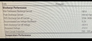
Manufacturer is saying that's ok???? But lists their BMS LVD at 10.4v
Especially if not recharged quickly.

Opinions are encouraged (y)
 
I've told my tale of CALB cells discharged to 0.6V/cell and their subsequent recovery. I think it depends on:

1) # of occurrences.
2) discharge current

Mine were pulled down to 0.6V under micro-amp currents.

Pulling down to low V @1C is probably way worse than 0.05C.

Most dumb BMS have a ±.05V or other tolerance associated with them. If they're all at the low end, I could see 2.2V the low end of expected, which is a smidge higher than 8.6V.

As with most situations, one shouldn't rely on the BMS to be the first means of protection, i.e., the equipment or system supplemental items (Victron battery protect) should be the first line of defense.

The fundamental objection is they don't meet spec or even to the low end of a reasonable tolerance range. If it hit 10V vs. 10.4V rated, I'd say that's tolerance/voltage calibration/accuracy.
 
What’s got me the most concerned is the listed BMS specs state 10.4v but them saying 8.6v is ok? This is a very popular and in demand drop in.
I have another post out asking for others test results on this battery but no responses yet. ?

FAF1B16D-67A0-407A-8F13-C14F5B7869A6.jpeg
 
The battery does not meet spec. That's grounds for a warranty claim. It doesn't just say 10.4V, it says >10.4V.

Also, I want to make sure the 8.6V you saw was based on a OCV measurement at the battery independent of loads. A voltage read through a heavy load and high resistance wiring would read lower than 10.4V even when the battery was safely at >10.4V.
 
I think you need to post a video of your test conditions and test equipment you are using. As long as each cell is not below 2V for very long it's fine. 2.5 is typical. 2.65V is ideal. Holding below 2V for a few weeks will permanently kill the cells. But if you have a substantial voltage drop, lvd occurs, and voltage recovers to 2.5V, it's fine.
 
The battery does not meet spec. That's grounds for a warranty claim. It doesn't just say 10.4V, it says >10.4V.

Also, I want to make sure the 8.6V you saw was based on a OCV measurement at the battery independent of loads. A voltage read through a heavy load and high resistance wiring would read lower than 10.4V even when the battery was safely at >10.4V.
The battery was not connected to any type of load. I thought maybe the BMS needed to be woken up from 8.6v so I used my PS but It didn't appear to be asleep just low and stated charging back up.
 
There are a few studies about this, here is one I found pretty easily: https://iopscience.iop.org/article/10.1149/1945-7111/ab7900

There is a transportation study covering lifepo4 storage that shows capacity loss and calendar aging rate. Couldnt find it on my phone but it's pertinent to this post.

Also, bms lvd should only trigger as last layer of protection. Inverter should have disconnected before bms did. Further, absorption voltage for charging should be controlled by the charge controller. Not the bms.
 
The battery was not connected to any type of load. I thought maybe the BMS needed to be woken up from 8.6v so I used my PS but It didn't appear to be asleep just low and stated charging back up.
Oh it arrived like that? What were the cell voltages? Sounds like a defective pack. Wow you must have found the first one. Is it accepting charge?
 
I think you need to post a video of your test conditions and test equipment you are using. As long as each cell is not below 2V for very long it's fine. 2.5 is typical. 2.65V is ideal. Holding below 2V for a few weeks will permanently kill the cells. But if you have a substantial voltage drop, lvd occurs, and voltage recovers to 2.5V, it's fine.
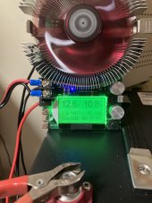
I am running another capacity test to see if it repeats the last LVD. Fully charged battery resting after 3 hrs at 13.4v. I did test the HVD by setting the PS at 15.1v 10a and the BMS disconnected at 14.8v as it should. Videos are challenging but I will post pics of capacity tester and DVM readings.
Start 27 min into test,

C8CF8E43-D5C9-4F35-A96F-A9793F14C835.jpeg

Oh it arrived like that? What were the cell voltages? Sounds like a defective pack. Wow you must have found the first one. Is it accepting charge?
No, no it arrived at 13.1v from shipping. I charged to 14.6v 10a before 1st capacity test. It is charging as it should. 8.6v LVD was what it was sitting at after cap. test.
BMS was not sleeping and began to charge up from that point.
 
I am running another capacity test to see if it repeats the last LVD. Fully charged battery resting after 3 hrs at 13.4v. I did test the HVD by setting the PS at 15.1v 10a and the BMS disconnected at 14.8v as it should. Videos are challenging but I will post pics of capacity tester and DVM readings.
Start 27 min into test,

View attachment 53232


No, no it arrived at 13.1v from shipping. I charged to 14.6v 10a before 1st capacity test. It is charging as it should. 8.6v LVD was what it was sitting at after cap. test.
BMS was not sleeping and began to charge up from that point.
How did you measure the voltage?
If it was the capacity tester please verify with a dvom.
 
Can you repeat the test and post the cell voltages? That would be very helpful.

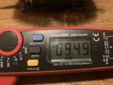
9.49/4 = 2.3725, which is fine for recovery. But that depends on how well the cells are balanced. Need individual cell voltages.
 
Can you repeat the test and post the cell voltages? That would be very helpful.

9.49/4 = 2.3725, which is fine for recovery. But that depends on how well the cells are balanced. Need individual cell voltages.
I am repeating the test as we speak (or tappity tap LOL) going to be a bit at <11a.
9.49v is after being on the charger for a few minutes.
I would have to open up the battery to get individual cell voltages.
I called Dexter and he said opening it up
Would be ok ? just no adjustment or settings on it. So I will get the cell voltages after this current test finishes.
I did see on your test @Will Prowse that you had to wake up the BMS after shut down. I did try that on mine but it didn’t appear to be asleep, just low voltage and began charging from 8.6v up to 9.49 after being connected for a few minutes.
All voltages were checked with my DVOM
and not the cap. tester.
 
@Will Prowse - excellent study! Without derailing the thread since it has been covered elsewhere, in the study, notice the emphasis about overhang (or lack of it) being a problem. I've known this since way back, and is one reason I always feel the need for prismatic cell-compression. I didn't want my cells "breathing" and getting out of overhang alignment. My cylindricals don't have this issue, (because I'm top balanced and not running their shallow-cycling lab test) unless they were made in some junk factory starting out that way.

@snoobler - actually a low current drain is more harmful than a 1C discharge to low voltage. In that situation, LFP recovers (to an extent). Part of the diffusion process. A faux-peukert if you will - at 1C demand, it can't intercalate fast enough. In a low current drain, where there IS plenty of time to intercalate there is no self-recovery, such as it is. Insidious how this can sneak up on you.

In either case, when dropping well down into the knee, recovery is best done with low recharge current until you reach your more comfortable voltage, or in my preferences, to nominal 3.2, maybe 3.1 at least just to be on the safe side after a low-voltage event to ensure that the surface recovery is uniform.

(This is from the old EV school where even if bottom-balanced to low voltage, and things were ok, the recharge process at high current killed many low-voltage cells prematurely.)

For me it is a law of reciprocals - there is not much usable chemical power going well down into the knee (either by design or by accident), therefore it is best to come out of it with little power/charge before applying full charge current.

These issues are all discussed elsewhere, so we'll return to regular programming - but was overjoyed to see Will link to that study!
 
Last edited:
@Will Prowse - excellent study! Without derailing the thread since it has been covered elsewhere, in the study, notice the emphasis about overhang (or lack of it) being a problem. I've known this since way back, and is one reason I always feel the need for prismatic cell-compression. I didn't want my cells "breathing" and getting out of overhang alignment. My cylindricals don't have this issue, (because I'm top balanced and not running their shallow-cycling lab test) unless they were made in some junk factory starting out that way.

@snoobler - actually a low current drain is more harmful than a 1C discharge to low voltage. In that situation, LFP recovers (to an extent). Part of the diffusion process. A faux-peukert if you will - at 1C demand, it can't intercalate fast enough. In a low current drain, where there IS plenty of time to intercalate there is no self-recovery, such as it is. Insidious how this can sneak up on you.

Perhaps, but I have 76 CALB 40Ah cells that were very slowly discharged to 0.6V, stayed there for months and recovered to capacities in line with 5 other cells stored at 3.30V.

I have a fair amount of battery experience and recharged them at about 0.005C until they recovered to 3.0V, and then I went to town on them.

These were installed and horrifyingly abused in a 10kWh Gen2 aftermarket plug in Prius kit in Phoenix PRIOR to being discharged to 0.6V.
 
You did the right thing. I may be confusing the two different issues in my message, which are separate.

I've done nearly the same but with Winston and GBS at dangerously low voltage levels - and found them that way, but perhaps for 2 weeks tops. It isn't so much the symptom, but the cure (high current recharge) that kills them. So like you I did a 0.005C recharge until it reached nominal voltage, and hammered away.

But like Will says - an inverter should kick off long before any BMS has to take action. Unrelated, but in the lead-acid world that's a no-no to even let your inverter act as the LVD, but better to use something else instead. Helped a lot of guys figure that out in lead-acid land thinking that hitting the backstop of the inverter LVD was ok each cycle, when obviously not.

But with LFP, I remember discovering that "hey, this might actually work using the inverter's lvd". :)
 
So have we come to a consensus regarding whether the BMS not cutting out per the spec is something we are going to brush off/ignore, and now suggest that another low-voltage shut-down device aside from the BMS be implemented into the system?

What happens if OP installed in his RV and left a 12v LED light on - What is the suggestion to make sure that the battery doesn't slowly go over-discharged and sit there to the point of cell damage? It's a system design aspect we must consider.
 
There are external programmable LVD's available to perform this function. I think for most though, they want the bms to do that. I used an external LVD when I was running banks top balanced with no balancers and my own fuses, HVD from the SCC and so forth.
 
So have we come to a consensus regarding whether the BMS not cutting out per the spec is something we are going to brush off/ignore, and now suggest that another low-voltage shut-down device aside from the BMS be implemented into the system?

Am I reading a different thread than you are? Who's brushing it off? I'm not. I'd be asking for an RMA just on principle.
 
Am I reading a different thread than you are? Who's brushing it off? I'm not. I'd be asking for an RMA just on principle.
This shutdown that OP is seeing is normal behavior on SOK's...At least so I've been told. Testing one now to confirm, but based on what I was told by SOK, this is regular behavior of their BMS.
 
@HighTechLab - we're not brushing this off either, you bring up a real-world issue!

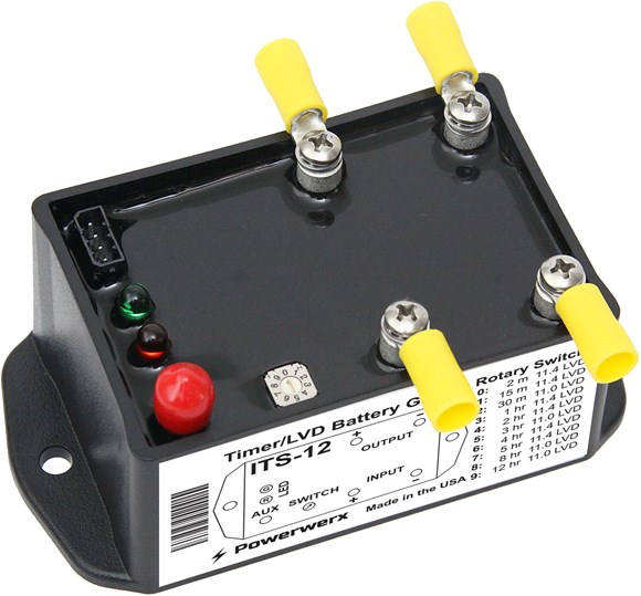
So, on a smaller scale, lets say you DO leave your small 12v load on the main bank and accidentally walk away. You *could* rely solely on the built-in bms, or something that I've used for that function to shut off the small loads - powerwerx battery guard


Adjust to your desired voltage needs. For large-current support, Blue Sea makes quite a few LVD's.

So not everybody needs one. Perhaps one thinks their drop-in bms LVD is too low and wants to stay out of the knee? You can use one of these. A higher current example, the m-LVD from Blue Sea


These are also common even with lead-acid for the same reason you mentioned - a forgotten about dc load killing your bank behind your back. Thing is, these devices also draw a small amount of power on their own.
 
I wonder why one would need or want the added expense to have an external LVD when it would be a very simple solution for the builders to set the disconnect to a common 10v> which is where 99.9% of LiFePo users use. Thereby keeping the battery at a safe low voltage condition. Why risk going lower with the chance it may or may not be detrimental in time?
does anyone using a smart BMS actually set their LiFePo LVD lower than 2.4v? And
WHY? I could see this for an occasional capacity test but only then.
@snoobler s and my point are the company’s specs on this battery are written as 10.4v LVD and their specs recommend 11.4v LVD. But they are stating 8.4v LVD is ok? ? Maybe these SOKs are revolutionary and can sustain the low settings…..im not an authority on that aspect.

Dexter @HighTechLab is currently running tests on a new one to solve this mystery and could prove to be a normal function with SOK.
I’ve emailed SOK asking Spec sheet so there’s no further problems or misunderstandings.

I have 5 other LiFePo BMSs all set for 10v> LVP for the longevity and protection of the expensive cells.
 
Last edited:
I agree with you MrNatural!

I suppose it all comes down to not relying on a single point of failure depending on how much of an investment you have in your cells. To me, a bms LVD is a "dead-man" switch, but for others it could be their primary.

Right now, and for the foreseeable next few months where my batts live, it is 85-105F or more, so I'm generally trying to keep things between the knees. In 4 years use in that environment, I may not want to trust solely in the bms - even if the manufacturer offers me a free replacement. :)

So I tend to set my LVD even higher than 11.4 to about 12v and just sleep better with an external as the primary.

At any rate, it's a personal decision based on a systems-level concern, and not just specs. To each his own.

It will be interesting to see the end results of the test.
 

diy solar

diy solar
Back
Top