diy solar

diy solar

What are Low Frequency Toroidal Inverters?

burgerking

New Member
Joined
Apr 6, 2022
Messages
368
Location
Subic, Philippines
So here I heard some inverters that are "low frequency toroidal inverters".

1. What are they? Example?
2. What is their advantage vs regular high frequency inverters?
3. Can toroidal inverters be high frequency?
4. And how do they synthesize sine wave?
 
No expert here, the toroidal transforms are "the best" and really help with heavy loads, and start ups. They are always low frequency and pure sinwave, best to my knowledge. I believe the sine wave is part of hardware/software. Check out generty solar. They have one and are made in the U.S.A. (with parts from china I'm sure) and they have a phone number you can call to talk to the owner himself. He will most likely call you back.
 
Last edited:
I'm also no expert and this simple explanation probably has holes. In the context of inverters, HF & LF refers to where the increase in voltage occurs. Both use high frequency switching circuits but HF generally runs at a higher frequency.

In HF the battery DC is boosted to something like 200 & 350VDC for 120 & 240VAC mains. This is then converted into a sinusoidal waveform for 50 & 60Hz. As this conversion is done at high voltage, the current is lower, and multiple small transformers are used.

LF is opposite in that the DC is converted to a sinusoidal waveform. This low voltage AC is increased to 120 or 240VAC through a transformer. As the voltage is low, the current is high, so a larger transformer is required. The large transformer is the main reason they can handle surge for multiple seconds instead of milliseconds.

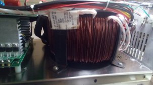
Main transformer types are EI (square style) or toroidal. Toroidals are better magnetically and can offer better idle current. A good toroidal inverter will idle at less than 20W.

Both designs have pros & cons so words like "best" are user defined.
 
toroidal inverters? Must be toroidal transformer, one in the same.
When I said "best" with the quotation Mark's I was hopeful people would read this as to what is generally said about them, but I was not necessarily telling anybody I agree.
 
I'm also no expert and this simple explanation probably has holes. In the context of inverters, HF & LF refers to where the increase in voltage occurs. Both use high frequency switching circuits but HF generally runs at a higher frequency.

In HF the battery DC is boosted to something like 200 & 350VDC for 120 & 240VAC mains. This is then converted into a sinusoidal waveform for 50 & 60Hz. As this conversion is done at high voltage, the current is lower, and multiple small transformers are used.

LF is opposite in that the DC is converted to a sinusoidal waveform. This low voltage AC is increased to 120 or 240VAC through a transformer. As the voltage is low, the current is high, so a larger transformer is required. The large transformer is the main reason they can handle surge for multiple seconds instead of milliseconds.

Main transformer types are EI (square style) or toroidal. Toroidals are better magnetically and can offer better idle current. A good toroidal inverter will idle at less than 20W.

Both designs have pros & cons so words like "best" are user defined.
Your explanation of differences is good but I wanted to nit-pick about the transformer size vs current:

Compared to high frequency design the low frequency transformer is large because of low frequency, not high currents.
(Low frequency needs large core and lots of wire turns around it)

Good surge handling is also sort of side-effect of the design, large transformer itself doesn't make it able to handle surges better.
Hmm. I was under the impression the large transformer itself provides the flywheel effect and allows long duration surges from the mass of material able to handle the eddy current heat generation for a longer period.

Small hf transformers do not have the copper and iron mass to allow and significant surge current or duration.
 
Maybe I should put up some samples:

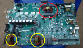
Here is the inverter board of Deye.
1658238303068.png

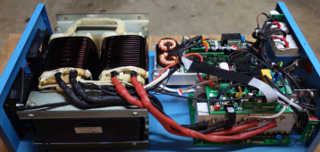
Here is SunGoldPower. I doubt this large transformer can be used in HF.
1658237532088.png

Your comments?
 
In LF inverter, the large transformer has its primary connected directly to the battery and in most designs high value capacitors are also used at the battery input terminals of the inverter. I believe this is one of the factors that contribute to its good surge handling capability. The power rating of the transformer basically determines the rating of the inverter.

Usually the transformer primary is made of heavy gauge wire/cable. Each of the primary ends are alternately switched to the battery + and battery - using high current power mosfets. In most designs the set of power mosfets are configured like an H (imagine the horizontal line of the H is the transformer primary). One pair of mosfet sets are driven at high frequency, one design I know uses around 23KHz I think. This high frequency mosfet set is connected to one terminal of the transformer primary through a choke. The other pair of mosfet sets connected to the other transformer primary terminal are driven at the low frequency of choice (50Hz or 60Hz). The secondary of the transformer drives the AC load. There is a capacitor across it and in conjunction with the choke filters out the 23Khz. Google EGS002 for some more info.
 
Last edited:
Some inverters use toroid inverters. The Sunny Islands and transformer type Sunny Boys I use have 60 Hz toroid transformers, which allows a bit higher efficiency than other type transformers.

High frequency inverters, including transformerless Sunny Boys, often use high frequency toroid inductors or transformers. (Like Deye pictures a couple posts above)

My measurements of transformer inductance, saturation, inrush indicate that despite being 50 or 150 lbs, the transformer stores extremely little energy, less than one 60 Hz AC current at full load. Applying full line voltage with no load, current rises to about 1/100th or less of rated current in the 8 milliseconds of 1/2 cycle. Applied for two half cycles, 16 milliseconds or one half cycle of 30 Hz, current gets twice that high then shoots up due to saturation - core can't store any more energy and current is limited by wire resistance not inductance.

I think surge current of low-frequency inverters is more about other design considerations, less about the big transformer and flywheel effect. Surge capability of HF inverter is probably limited by max current of its boost converter. That could be sized 2x or 3x if desired, based on its saturation current. Heat handling is something that could be pushed for surge, but not saturation.

A transformer can handle high current in primary without saturating because high current opposite direction in secondary cancels magnetic field.
An inductor for boost converter has to store energy for each high frequency cycle with its inductance. I think that is the limit. But, design could switch it at twice the frequency to deliver twice the power (until things overheat.) So I would guess surge capability is more a firmware choice.
 
Hmm. I was under the impression the large transformer itself provides the flywheel effect and allows long duration surges from the mass of material able to handle the eddy current heat generation for a longer period.

Small hf transformers do not have the copper and iron mass to allow and significant surge current or duration.
No, this is some nonsense spread by unmentioned manufacturer. Flywheeling effect is close to zero in typical "modern" LF inverter.
(low efficiency stone age magnetic resonance design from -70's could have some flywheeling effect)

WAG: typical HF inverter surge rating is not even limited by the HF transformer but other components.
 
The basics of HF vs LF inverters:

In a HF inverter the DC voltage is first boosted with DC/DC boost converter (48vdc to 110vdc, well really more like 170vdc because the H-bridge needs headroom to account for load voltage drop, etc) before being inverted.

In a LF inverter the DC voltage is first inverted (converted into an AC sine wave) then fed into a large step-up transformer. Basically the Transformer is doing the boosting of the voltage in the AC domain.

What's the deal? Well a large Transformer can typically do the boosting (step up) job with less stress than most DC/DC boost converters.

HF inverters tend to be more efficient at idle.
 
Last edited:
A good power transformer has very little percentage inductive storage flywheel effect. It should have tightly coupled input primary winding to secondary output winding to magnetically pull the secondary loading along.

A flyback transformer, more appropriately referred as coupled inductors, rely on inductive energy storage. These are often used in high frequency switching power supplies. They usually have a core air gap to purposely increase self inductance dramatically. In a toroid configuration they are made with powered iron with separating binder glue to effectively have a distributed air gap.

The high frequency E-core transformer used for battery to high voltage DC converter in HF inverters are true power transformers without any air gaps. Their ferrite material has a very abrupt core saturation, so they are more vulnerable to surge overload. When the core saturates, they become very low inductance shorts across battery side input MOSFET H-bridge causing MOSFET's current to shoot up to destructive levels. It is also very important the duty cycle of switching be symmetrical to prevent magnetically biasing the core which reduces the saturation point of core.

Toroid power transformers have slightly lower leakage inductance. This improves primary to secondary side coupling a little and reduces external magnetic field leakage reducing pickup on nearby circuitry. They were originally used for high priced stereo audio equipment to reduce 60 Hz hum pickup in audio.

For a low freq inverter it pretty much does not matter if it is toroid or E-core transformer. With PWM sinewave chopping there has to be some series inductance along with filter capacitor to smooth out the PWM to sinewave output. This is usually an extra series inductor these days.

Outback's original sinewave PWM low frequency inverter used E-core transformer purposely made with thicker varnish between laminates of E-core to increase self leakage inductance. Counter to normal power transformer design, this provides some increase in series leakage inductance within transformer core so all they needed was a capacitor across output secondary of transformer to filter PWM sinewave chopping.

Low frequency silicon-iron cores are limited in PWM switching frequency to less than about 12 kHz, where a high frequency ferrite transformer can be 25 kHz or higher putting them out of human hearing range.

From a practical cost point of view, it is usually cheaper to manufacturer to buy a high-volume manufacturing standard E-core power transformer design and add an external series inductor on primary side then get a special transformer build design that has greater leakage inductance just to eliminate the extra inductor.

Toroid power transformers are more difficult to manufacture as the coil winding process is much more complicated. It requires a winding loom with pre-cut wire lengths put on a spindle that passes through the center of toroid like a sewing machine.
 
.........

Low frequency silicon-iron cores are limited in PWM switching frequency to less than about 12 kHz, where a high frequency ferrite transformer can be 25 kHz or higher putting them out of human hearing range.
.........
That was my concern too when I was designing my inverter using EG8010 chip with its 23.4KHz pwm. But because I was using a series choke, it was not an issue. If I remember, Warpspeed said that what goes through the toroid is only the low frequency and the high frequency goes through the choke. I verified this with an oscilloscope. Selection of the choke material, inductance, and saturation point is one of the critical part of the design.
 
Ebay has some nice ones....I bought a 500 watt one for some testing for $60

Just search "triad magnetics toroidal"
 
See, I knew there were people on here that knew way more about this than I do. That's the reason I listed a manufacture that could be called, then he could explain.
I was under the impression that large Toroid, massave transformers were " better".
Thanks fo
r the explanation.
 
Back
Top