Jeff From NJ
New Member
- Joined
- Dec 2, 2021
- Messages
- 68
I built a homebrew system around a Chinese split phase solar inverter and would appreciate someone taking a look and checking to see if I have any errors prior to powering it up. I know there are several ways to do this, but my goal has been to add a generator option into the mix and that sort of led me to the setup I am currently building.
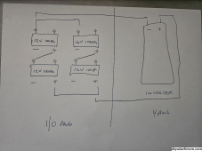
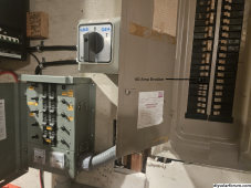
The design of the system is to have the inverter connect to the 6 panels (for now), the grid, through the 30 amp manual transfer switch which comes out of a 60Amp breaker on the main board, and four LiFePO4 batteries (wired 24v 100Ah). Should the grid go down, and there's no sun, and I have no battery power left, I have a large manual A/B switch that switches the house from the inverter to a generator via the 30 Amp manual transfer switch which is connected to the house breaker box and has all the "important" circuits powered through it via a 60 Amp breaker in the main house breaker panel.
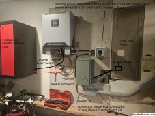
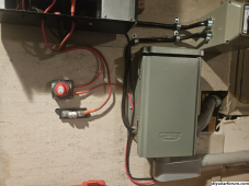
I've included the specs and several photos of the almost completed system showing the wiring and components.
Here are all the specs:
2S3P panels - six (260W, 30.6V, 8.5A)
four 12V 100MAh LiFePO4 batteries (wired together for 24v 100Ah)
SNAD 4KW 24VDC solar inverter with charger Pure Sine Wave ,split phases Output: 120V 240AC 60Hz
Rotary Changeover Switch - 660V 125A 3 Position 3 Phase - connecting grid and generator to inverter via Conn. Elect. manual transfer switch
On/Off Switch for panels - 12-48V Battery Cut Switch - 275 A continuous at DC 12V, 455 A intermittent at DC 12V, 1250 A momentary at DC 12V
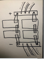
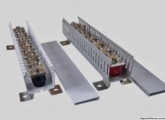
Bus Bar - 600 amp 12 stud black/red - Not sure if I should get something like this
Battery Switch - 600A On/Off - For batteries
4 AWG for batteries and wiring between components
10 AWG wire between solar panels and on/off switch
Class T with 200 amp, 250AC/DC250V Fuse Block - after 600amp switch connected to batteries (or bus bar) and before inverter
Connecticut Electric EGS107501G2KIT 30 Amp Manual Transfer Switch Kit - to connect generator and inverter to important circuits
I am concerned about the entire setup, and afraid things are going to go up in smoke (including me when I switch on the breaker or the panels). I believe I am going quite a bit outside the norm, especially for a first attempt and would love to hear guidance from those that are more knowledgeable. I am also currently questioning if I should wire the four batteries together via 4AWG wire to get 24v 100Ah, or to connect them via two buss bars and then take the negative to the inverter and the positive bus bar to the 600Amp switch and then the T-fuse and then over to the the inverter for purposes of even recharging and discharging of batteries - it seems wiring the batteries together with 4Awg will create a charging/discharging/balancing issue. I saw a pair of 600Amp rack mounted bus bars for $80 that seems to fit the bill, but before walking down that path, and the expense for wire and the bars, wanted thoughts.
So, I was hoping someone would look over the setup prior to powering up to see if I am missing something or if I made any errors, and if it's not too much, letting me know if using two bus bars from the battery bank will achieve my goal of better charge/discharge or if I should just wire the batteries together for 24V 100Ah and forget the bus bars.
Really (truly) appreciate your time.
Thanks
Jeff


Last edited:


