diy solar

diy solar

Would someone mind reviewing my setup BEFORE I turn on the system ;-)

Jeff From NJ

New Member
Joined
Dec 2, 2021
Messages
68
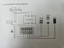
I built a system around an MPPT Hybrid solar inverter I bought from China - 4KW 24VDC solar inverter with charger - pure sine wave, split phase output: 120V 240 AC 60Hz, and will be connecting the Inverter to a 30 Amp Chicago Electric EGS107501G2KIT manual transfer switch box that I have my generator connected to and a limited number of breakers to power important items in the house and would love a set of eyes to tell me if I need to change something before powering things up.

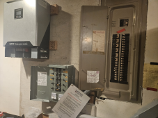
One of the photos attached shows the system as it stands, I will be connecting four 12V 100Ah LifePO4 batteries to the system, in series/parallel so I will get 24 V 100Ah power and will attach a 200 amp T Fuse anl with block to the + wire off the batteries before connecting the positive and negative wires to the inverter through the inverters battery input.

I currently have 6 Trina TSM-260PD05.08 (260W PV Module, MC4, PV Wire, 35mm Black Frame with White Backsheet, BOW, 60 Cell Poly, 15A Fuse, 1000VDC) solar panels that will connect to a 12-48 Volt Battery switch (solar disconnect) and then into the Inverter at the appropriate location. The plan is to wire the panels and connect the negative (-) of the solar panels to the disconnect, switch the disconnect OFF, and then wire the positive and negative panels into the inverter.

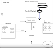
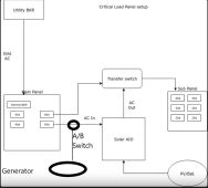
The last step, and my biggest question, is how to wire the grid power into the inverter so the box will properly control the power. I plan on having the house, via the manual disconnect generator box, attach to the inverter with the hope that I will power those items in the manual disconnect box first from solar panels, then from battery power, and then from the grid, or if it is down, from the generator which is directly connected to the manual disconnect box. My question is, I don't see an obvious place in the manual disconnect to jump to the solar inverter. If I connect the inverter to the grid, via the two Hots in my main house breaker box, then the inverter would operate properly except if the grid went down. After the panels stopped producing electricity and the batteries were drained, the generator, which is directly connected to the manual disconnect, would not send power to the inverter so the inverter, I believe, would never know the generator is operating (while the grid is down) and after my panels and batteries were exhausted, the inverter would not realize there is power available via the generator.

Is there a better way to hook this all up so the inverter, via the AC Input (Hot 1/Hot 2), could control everything? I'm sure there is a way but I am simply missing the obvious.

Thanks everyone!
 

Attachments

  • 20230630_131136.png
    20230630_131136.png
    1.3 MB · Views: 43
  • 20230630_114948.png
    20230630_114948.png
    1.6 MB · Views: 42
About the simplest method is to feed your AC in on the AIO from the Main panel and use it to supply the AC in to the Reliance transfer control panel. Your AIO has an auto transfer switch that allows AC bypass and operating mode preference where you can set it to prefer solar/battery first this means the AC supply to your transfer box would be either grid or inverter. The generator would just stay as the the alternate feed as presently wired.

You do mention that it is hybrid but sometimes that does not mean it is grid tie. Grid tie would require additional thought and setup since it could back feed the Main otherwise.
 
The transfer box is not fed from the 220 Hot off the breaker panel. The transfer box has each circuit in it jumped individually from the breaker box so we don't have a full connection from the grid. I wonder if I could just jump from the 220 in on the main breaker to the Inverters Hot in.

I wonder if I did that, if the grid would go down, the inverter would know, but how would the generator, which is connected to the manual transfer box, be able to be used automatically.
 
Last edited:
Sounds like you need a new plan. And perhaps a different critical loads panel and transfer setup.

Some AIO's have a autostart ability for generators with a separate AC in from Gen. Other can auto start and make use of a ATS for AC in supply. The AIO's AC out than feeds the critical load panel.
 
Someone on Amazon said the manual transfer can be connected to the inverter instead of the generator to make it work with solar, of course losing the ability to tie in a generator. I was thinking that the solution would be to get a switch and connect the generator to one side, the inverter to one side, and both of them ties to the manual transfer box. This way everything works as required automatically with the inverter until there is no power from the grid. If that occurs, once I run out of solar or battery, I can just flip the manual switch and change from the inverter to the generator and power up the manual transfer box.

I bet there is even an automatic switch that can sense both the grids power and the generators (if turned on) and only allow the side that has power to connect to the inverter
 
A typical setup for an off grid AIO with a transfer switch to isolate it is the diagram below. Adding in a generator would require a additional transfer switch on the AC in portion of the AIO (assuming that you are running a 240v split phase output generator).


Critical Load panel.png
 
"reviewing my setup BEFORE I turn on the system"

Before turning on breakers, use DMM to check voltage and polarity, make sure it is what inverter expects. (AC, battery, PV)

I have wired a breaker panel with L1 to N, and N to L1. So easy to mix things up, for some configurations (that was a 100A panel, no main breaker.)

People here have wired PV backwards. Also battery.

Note Voc from PV, double-check that with cold temperature calculation it won't exceed maximum voltage.

Lithium, Class-T fuse, inverter. Do you have a precharge mechanism, to avoid blowing the fuse or stressing the capacitors due to inrush current?

Are the batteries compatible with series 24V connection?
Fully charge each before connecting in series, since they are likely not at 100% SoC and not at same Soc.

Determine max/min voltage settings of BMS. After connecting just batteries to inverter (no loads, no PV), adjust max/min voltage of inverter to get desired operation (doesn't cause BMS to disconnect, and charges to sufficient voltage to allow balancing.)

transfer switch has a lot of wiring complexity, so make sure it is out of the picture and have a simple load available when bringing system up.

Make sure screws are snugged on wires. I find stranded wires settle, so I wiggle in a manner that rotates wire under screw and keep tightening until it stops moving.

When operating under load, check for excessive voltage drops. After running for a long while, use IR thermometer or camera to check tempratures.
 
Where would the generator fit in your chart, connected to the transfer switch?
It is not shown but as I mentioned it would connect before the (AC in) of the AIO.
Thus the main connects on one side of the transfer switch, Generator to the other. Output of switch to (AC in) of the AIO.
 
So like this, I could put a manual switch in front of the generator before the manual transfer case
 

Attachments

  • Capture.png
    Capture.png
    84.6 KB · Views: 6
So like this, I could put a manual switch in front of the generator before the manual transfer case
No not like that. Doing it as you picture would not allow your generator to power the AIO's charger to recharge your batteries.

Feeding in to the AIO from either the Main or the Generator allows either one to supply the AIO for charging while AC Bypass mode. The only concern is if the generators out put is acceptable to the AIO. (some of them are finicky and need a inverter generator to supply.)
 
Like this? With an A/B switch so I could switch to generator if he grid is down?
 

Attachments

  • Capture.png
    Capture.png
    81.6 KB · Views: 14
Are "A/B Switch" and "Transfer Switch" same function?

Transfer switches could be nice, maybe expensive and large. I use interlocked breakers, typically meant for generator input. More expensive than a piece of sheet metal should be, but cheap compared to transfer switches.

You could use one interlocked breaker on sub panel to select between AIO and Main Panel.
A second interlocked breaker on Main Panel to select between Grid and Generator.

Select the exact models that fit your panels.

1688220323927.png 1688220436558.png
 
Are "A/B Switch" and "Transfer Switch" same function?

Transfer switches could be nice, maybe expensive and large. I use interlocked breakers, typically meant for generator input. More expensive than a piece of sheet metal should be, but cheap compared to transfer switches.

You could use one interlocked breaker on sub panel to select between AIO and Main Panel.
A second interlocked breaker on Main Panel to select between Grid and Generator.

Select the exact models that fit your panels.

View attachment 155277 View attachment 155279
I already have a Connecticut Electric EGS107501G2KIT ($155 on Ebay) which moves the circuits from the breaker box and comes with an outside generator plug input. The manual transfer box essentially jumps from the breaker box to itself and when there is no power from the grid, you plug your generator into the manual transfer switch, flip the manual transfer switch to "generator" and the generator will only power those circuits you've moved over. Similar result to the lockout you are showing, but the manual transfer box will not allow the generator to backfeed the breaker box, so no need to have the lockout.

My conversation about the A/B switch is because I am trying to tie the AIO inverter into the manual transfer box and the A/B will allow me to move the AIO inverter to generator power if the grid is down. Without the A/B, I could use grid power, solar, battery, but no generator.
 
Back
Top