diy solar

diy solar

Xuba cells with Laser welded bus bars

pmtco2

New Member
Joined
Nov 23, 2020
Messages
30
Been a lurker here for a few months, I'd like to start by thanking this community for contributing to all the wonderful knowledge on this site.

I am still somewhat new to this, but I have spent time reading most of the long threads here in their entirety, and watching all of Will's vids. I'll try to be concise, but please forgive if my terminology is a bit off.

Back in November, I ordered 2 "partially pre fab" 12v LifePo4's from Xuba (they have not yet arrived). They are 4s 176AH, with pre installed bus bars, wired in series. I plan to use them in an RV solar setup with a couple Sunpower panels and a 2500w inverter.

Link: https://www.alibaba.com/product-detail/Suitable-for-12V-24V-48V-solar_1600154053852.html

Here's a link to the 280AH Xuba's in the same setup: https://www.alibaba.com/product-det...html?spm=a2700.shop_index.89.7.202db917TDLMO1

I chose these because the bus bars are not only pre installed, they are also laser welded to the terminals. This seems like an inherently better connection to the soft aluminum terminals on most of these cells, and of course, zero risk I strip any of them during installation.

So I have searched, and can't seem to fid any posts where folks have experience with these. If I have missed them, please let me know....but if not, I have a few questions.

I plan to rig these in a 4s2p configuration, with 2 of the 120a JBDs as the BMS.

What's the best way to attach the BMS leads to the cells? My first thought is to drill a small hole in each bus bar, and use a self tapping screw with a lock washer to attach the leads. But, that seems like it might be dangerous with them attached to live cells.

I could also use a clip (or clamp?) of some sort, but I am not sure that would stay put in a bouncy travel trailer. And, of course, any other suggestions....I am all ears.

Also, I assume these cells, despite being already partially pre-fabbed into a battery pack, are not balanced. And obviously, I can't pull them apart to run them in parallels. So, what do I do? Attach the BMS, charge 'em up to 3.6v and let the BMS trickle balance? I am not in a huge hurry, but I was hoping for a solution that didn't take months at 60mA.

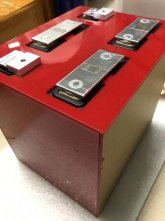
Attached a pic of the actual battery the Xuba folks sent me via email.

Thanks in advance for the help.
BDF61F220F44207A5396CE67625DDAE5.jpg
 
Install the BMS and charge until one cell reaches 3.6V. Then take a bench power supply and bring the remaining cells up to 3.6V.
 
I wasn't sure that was possible if the cells were in series.

How would you attach the BMS leads?
 
Those bus bars appear to have a solder pad on the middle. Which is probably plated to accept copper wire and tin solder.

Otherwise drill and tap a small hole, or use a screw clamp.
 
Last edited:
Ah, is that what that rough patch is? Thanks, I was curious why they wouldn't provide a mechanism to attach the BMS leads, that must be it.

I have searched all over for an aluminum screw clamp that looks like the right size. Best I could find was several varieties of copper-based ground clamps that appear to be way too big for this use.
 
It appears to be, but interestingly....I don't see it stated on the web page anywhere.
 
If they are Aluminuim then you cannot soder the wire to the bar using solder, you may have to drill and tap the hole so you can attach the BMS terninla to it. They should have added the tapped hole for the BMS.
 
I'm still not clear on how I balance these packs. All the procedures I have seen involve either bench charging the cells in parallel, or hooking up the BMS and just let the BMS balance them over time.

Since wiring these cells in parallel is not an option, seems I should (per Luthj) charging each pack (via the BMS) until the first cell hits 3.65v, and then....what? How do bring the other 3 cells up while they are in series?

Also, I know I read it somewhere on this forum, and I can't find it now....the JBD balancing function, is it just bleeding 50-60ma current to bring the "top" cells down to the rest? If that's correct, then it seems that may not really help either if have a pack with 1 of 4 cells charged up to 3.65.

I could be missing something very fundamental here about the BMS or the top balancing process....please let me know if I am. I just don't see how I can affect the voltage of an individual pack whilst they are in series.

I think I am going to drill/tap the BMS leads to the bus bars. Seems like that would more reliable in an RV than a solder job, if solder is even possible (especially with my crappy soldering ability).
 
How do bring the other 3 cells up while they are in series?

Once the first cell hits 3.65V stop charging the pack. Then take the leads from your bench power supply (set to 3.65V), and connect them to one of the low cells. When it hits 3.65V, switch to the next cell. Repeat until they have all been charged to 3.65V. The cells will settle a bit after you remove the charger, but that's okay.

Another option is to set your charger to say 3-4A and charge the pack as 4S, then use a 1ohm 50W resistor across each of the high cells. Watch the system like a hawk, and add resistors to each high cell as they start to get ahead of the low cells. Eventually you will have all but one cell with a resistor, and then the last cell hits 3.6V, you terminate the charge. This method is fiddly though, and you need to have the BMS connected the whole time to prevent overcharging.
 
Last edited:
Ok, possible stupid question here.

Obviously the negative terminal of said cell is wired to the positive terminal of the next cell over. Connecting the negative lead from the bench charger to that bus bar, and the positive lead to the next bus bar over won't result in any fireworks?

I trust your advice, I just like to understand what I am doing.
 
Connecting the negative lead from the bench charger to that bus bar, and the positive lead to the next bus bar over won't result in any fireworks?

Nope, as long as the other terminal of the adjacent cells isn't connected to the power source, no current will flow in the adjacent cells. Just make sure you get your polarity right before connecting the power supply.
 
Maybe it's an optical illusion but the trailing edges of the first two bus bars look warped, not flat.

My opinion is that I would never order my cells with bus bars welded on.

To attach the balance leads, drill a hole in the bus bar and tap it for threads. Or, instead of tapping threads, slide a nut under the bus bar and thread the screw into the nut.
 
Looking at the photo, I believe these pads are friction welded tin plated copper. If so they would be used to solder balance leads. You would need a higher output Iron though.

1610470569842.png
 
My opinion is that I would never order my cells with bus bars welded on.

Why is that?

I have read a few threads about issues stripping the terminal threads, and conductivity issues with stacking BMS leads on the posts with bus bars. This seems like it would resolve both of those problems.
 
Why is that?

I have read a few threads about issues stripping the terminal threads, and conductivity issues with stacking BMS leads on the posts with bus bars. This seems like it would resolve both of those problems.

Lack of flexibility. Maybe I want to change to a 2p4s or 8s battery. What happens if one of the middle cells is bad?

If you keep a light touch on the terminal threads there are no problems.
 
Oivey, people will get these and the threads on discussing them will be out of this world.
If the cells are not actually Matched, Batched & Binned (at those prices they are NOT) the stuff will hit the fan with runners.

Drilled & Tapped for Screws = GOOD.
Laser Welded "Flush" terminals = Very Good !
Welded busbars only on Matched & Binned Cells (you cannot separate them and if you do, your grinding, drilling & tapping). IS WONDERFUL IF they are all good & matched cells.

Yeah for $625 delivered, its somewhat a leap of faith. And no, I have no illusions they are matched and batched at that price.

I wanted to eliminate a variable that might contribute to failure from my inexperience. To HRTKD's point, I am trading some flexibility here with not having to worry about a mechanical aspect of this build that I'm not 100% comfortable with. Maybe that's a little of an overreaction, but seems that as long as I secure these packs properly, there's little to no chance of these connections (both BMS and welded) shaking loose because I'm a little unsure of my ability with a torque wrench.
 
Using an in-lb torque wrench is pretty easy. Its about as difficult as using a mechanical control microwave.
 
Back
Top