diy solar

diy solar

Xuba Electronics: DEAL - 280AH LiFePo4 cells. Purchase & Review

I have 8 of these 280ah cells on order. I am wondering if anyone is going to make, or is interested in, a 3-d printer design to hold these in a pack. I am thinking that it should be possible to design something like the Fortune cell plastic top and bottom that Will was excited about (OK, he's always excited)

See https://diysolarforum.com/threads/280ah-battery-top-and-bottom-support-design.5261/
 
60590757446__E95913EF-5E0B-4448-A0A0-7D1FB92C1718.jpg60591620607__F514FA3D-FD36-4734-BA17-9A06D5C4C3F8.jpgIMG_3786.jpeg
Love those 3D printed modular cases!
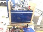
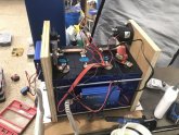
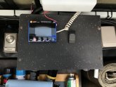
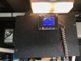
Still, I built a very simple battery box which is 12"x8" x 11" h) with 3/4" plywood, 1/4" threaded rod, 1" x 1" aluminum angle and a cutup cutting board for the lid from Target. The main load relay Gigavac and charge SSR are contained within the box. The carling switch is manual relay kill, so I can put the battery in sleep mode (<1.0 amp flow).
I used threaded rod to retain the shunt and mount the relay, also. I connected to the battery to the shunt and from the fuse to the contactor relay with bent up busbar copper. This was about $20 in hardware / parts plus scrap plywood.
Mounting feet are aluminum angle. I placed 3/16" rubber pad which I cut to fit to reduce a bit of vibration against the framerail. I made a template and drilled the framerail and install thick wall rivnuts so I could bolt it in place.
Lots of ways to do this.
Hope this might help someone.
BTW - If this post is not sufficiently relevant, I can extract and post elsewhere.
 

Attachments

  • IMG_3772.jpeg
    IMG_3772.jpeg
    77.9 KB · Views: 17
Looks Awesome. I notice Chargery's Active Style of BMS that balance cell more quickly (by transfers of watts from higher v cells to lower v cells vs common resistance draw down of higher volt cells, or something like that) with digital interface.

One Forum Question: Would it be better to have a thin space between the battery cells? for higher amp draws or charge cycles? that could heat and possible expand the battery cells. Seem like a space would keep cells cooler if the had any reason to heat up. I am considering a small space when put mine together, thinking it would be a hair safer. I might go with a layers or tow of VHT tape for such spacing. I notice that spacing built into some battery packs. ... Food for Discussion? ... or ... at least food for thought and options.
 
Capt Bill,
What are your loads? Mine is in an RV. High draw might be 120 amps, which is substantially less than 1C. But that might account for 15 to 30 minutes / day.
I ran this type of load for 20 minutes just to test and saw zero change in battery temp. Not sure this was long enough to hit steady state, but I think the data might be helpful.
I'd probably add an air gaps if I planned high sustained cycle loads (1C - ish). But someone else probably has more data to support than me.

Doug
 
Doug, ... since you asked, I re did my notes to make em clearer:

My Notes from my BMS/ research/ needs for 240v split phase: for
Up to two LV2424 All In One Units connected to Same 24v LifePO4 set
Looking at Max Amp draws possible for my wiring/ Fuses/ Breakers/ BMS choices:

Max Draw (doubt this would happen often/ but want capability) for 2400 Watt rated Max Output
for 20 amp @ 120 v ac draw on 24 volt dc @ about 85% efficiency ? might be
25 x 120 = 3000 watts
= 3000 Watts / 24 v = Max Draw : 125 Amps @ 24 v dc battery
= Max Draw ... for One - All In One LV2424 unit

X 2 when configured with two LV2424 All In One units for 240V Split phase (on same battery bank!
= Max Draw 250 Amp on same LifePO4

Need to examine capabilities of LifePO4s = Max 1C (still researching n learning
my LV2424s have about 28 adjustments for configuration
(going by memory ... so would adjust max amp downward to Max solar Input of 160 Amp @ <24v from 4000 Watts of Solar Array

************
FOR MAX CHARGE INPUT on 8 x 3.2v 280Ah (1st version) 24vdc LifePO4 battery set
Solar Only In Max 80 Amp / for two LV2424 = 160 Amp Max Input to Battery (max I would configure for use)

Other specs: Grid Charge Max = 60 Amp /x two LV2424 = 120 Max Amp Charge Input from grid or generator(s).
Total Charge Max w Solar + Grid = 140 Amp Charge / for two LV2424 = Largest MAX ever: 280 Charge Amps
(will configure for solar only, and switch over to grid input seldom-ally)
 
Captain!-
I suspect what matters also is time at 1C.
If you might run air conditioner at 75% duty cycle for hours it would be different than five minutes of microwave to boil water for your tea.
Then again your bank capacity wouldn’t support high C rate load for hours.
I think you can predict heat generated by pack impedance. Heat can then translate to pack delta F over time.
If you are grid charging suspect you could set at lower rate as if overnighting at guest dock.
 
Looks Awesome. I notice Chargery's Active Style of BMS that balance cell more quickly (by transfers of watts from higher v cells to lower v cells vs common resistance draw down of higher volt cells, or something like that) with digital interface.

One Forum Question: Would it be better to have a thin space between the battery cells? for higher amp draws or charge cycles? that could heat and possible expand the battery cells. Seem like a space would keep cells cooler if the had any reason to heat up. I am considering a small space when put mine together, thinking it would be a hair safer. I might go with a layers or tow of VHT tape for such spacing. I notice that spacing built into some battery packs. ... Food for Discussion? ... or ... at least food for thought and options.

For mobile operations i will put/tape these between the batteries to allow for airflow .. https://www.amazon.com/Troxell-USA-...1&keywords=horshoes+1/8&qid=1586142948&sr=8-4
 
View attachment 10348View attachment 10349View attachment 10352
Love those 3D printed modular cases!
Still, I built a very simple battery box which is 12"x8" x 11" h) with 3/4" plywood, 1/4" threaded rod, 1" x 1" aluminum angle and a cutup cutting board for the lid from Target. The main load relay Gigavac and charge SSR are contained within the box. The carling switch is manual relay kill, so I can put the battery in sleep mode (<1.0 amp flow).
I used threaded rod to retain the shunt and mount the relay, also. I connected to the battery to the shunt and from the fuse to the contactor relay with bent up busbar copper. This was about $20 in hardware / parts plus scrap plywood.
Mounting feet are aluminum angle. I placed 3/16" rubber pad which I cut to fit to reduce a bit of vibration against the framerail. I made a template and drilled the framerail and install thick wall rivnuts so I could bolt it in place.
Lots of ways to do this.
Hope this might help someone.
BTW - If this post is not sufficiently relevant, I can extract and post elsewhere.
Where did you find the terminal fuse block for a M6/1/4" terminal stud/screw? I can find them with a 5/16" and a 3/8" mounting hole.
 
I didn’t. Used 5/16”. With a larger stainless washer. Figured energy transfer comes from physical contact to terminal. So this terminal has same clamping force as all others.
Is it a CBBF-MBC mounting bar? That has a 1/4"-20 stud, but I can't find the terminal mounting hole size listed anywhere on the web or their catalog. One would think it would be listed somewhere, but I haven't found it. What size fuse are you running?
 
Yesterday I used 2 6" strips of Gorilla HD double side tape per group of cells to hold my cells together and then connected everything back up.

Here goes my first test I moved the battery into my bedroom and connected it to my ICECO VL60 fridge/freezer and unplugged the 110VAC.
At 11:45PM 04/06, I'm starting with the battery at 13.9V. I have 24 cold cans of soda in the fridge side and a frozen gallon of water in the freezer side. Will check it every so often to see what it is doing.

The compressor just cycled on. It pulled 4.42A and quickly dropped to 3.24A. If it's like when it was on AC, it should run for around 10 minutes twice an hour.

I'm using the voltage on the fridge screen...

ETA:
04/07. 12:45AM.... 13.5V.
If I understand this correctly, it's just knocking the top charge off and should stabilize real soon.
If I have that wrong, I'm sure someone will correct me. As long as the forum software lets me, I'll ETA, till I go to bed.

Battery Test.jpg
 
Last edited:
Is it a CBBF-MBC mounting bar? That has a 1/4"-20 stud, but I can't find the terminal mounting hole size listed anywhere on the web or their catalog. One would think it would be listed somewhere, but I haven't found it. What size fuse are you running?
I have a 300A fuse since my inverter is 2800W.
I looked here and it seems there are lots of fuse options that suit SBBF-MBC
Page 36.
That's probably a better setup than what I have, since mine is slightly oversized.

I have the Chargery BMS set to cut off current a bit lower, but with a 15second delay. This should accommodate for any startup surge.
Note, I don't think a short surge >300A on the fuse burns it up. I remember reading a current vs. time curve on the mfg website about their fuses.
I did buy a spare fuse to have on hand.

Good luck with your testing!

Doug
 
Still holding strong at 13.4V. Installed a padded insulated cover on the fridge a little while ago. That should make it a little more efficient. After this test is over, I'm going to run one with both zones set to fridge and see how much less power it uses that way.
 
I have 8 of these 280ah cells on order. I am wondering if anyone is going to make, or is interested in, a 3-d printer design to hold these in a pack. I am thinking that it should be possible to design something like the Fortune cell plastic top and bottom that Will was excited about (OK, he's always excited)

I'm working on a design right now with active cooling around each cell, I'm just getting started so this design may change greatly before its all said and done.

FYI I'll start a new thread as to not hijack this one.


1586347526234.png
 
Last edited:
My UPS tracking finally went live today and my 16x are planned to be delivered early next week. I ordered them on Feb 4 and they shipped by train on Feb 20 (Amy did say they would not be sent earlier given their lockdown). And then as they were on their way most of Europe decided to shut down too...

I'm very happy with Xuba support though, and I'm not in a rush.
 
I'm working on a design right now with active cooling
What are your thoughts regarding active cooling, and what about heating?
FYI I'll start a new thread as to not hijack this one.
OK, post a link. I agree that this design will apply towards all the aluminum lifpo cells and maybe this thread is more about the 280ah/Xuba. They must all come from the same factory. They are always blue.
 
What are your thoughts regarding active cooling, and what about heating?

OK, post a link. I agree that this design will apply towards all the aluminum lifpo cells and maybe this thread is more about the 280ah/Xuba. They must all come from the same factory. They are always blue.
Many companies make "Blue-ees", it is just a heat shrink vinyl wrap over the casing. The ones Xuba is selling are made by EVE.


Heat is ONLY an issue is High Draw / Load situations or when Fast Charging with High Amperage. In a Typical storage type of application which is using 100A or less on average, that will barely "warm" the cells. You would have t be pushing them at minimum 1C to 2C for heat to become a noticeable issue. Remember that LFP likes the same temperatures that humans do.
 
Many companies make "Blue-ees", it is just a heat shrink vinyl wrap over the casing. The ones Xuba is selling are made by EVE.
Oh, I thought these were aluminum cases.
Heat is ONLY an issue is High Draw / Load situations or when Fast Charging with High Amperage. In a Typical storage type of application which is using 100A or less on average, that will barely "warm" the cells. You would have t be pushing them at minimum 1C to 2C for heat to become a noticeable issue. Remember that LFP likes the same temperatures that humans do.
I know.

Active cooling will help when my RV is heating up in storage or when we are out roaming around. Active heating will help when my RV in storage in the winter, or when we are asleep under loads of blankets.
 
Oh, I thought these were aluminum cases.

I know.

Active cooling will help when my RV is heating up in storage or when we are out roaming around. Active heating will help when my RV in storage in the winter, or when we are asleep under loads of blankets.
They are. The Blue is a shrink wrap used to cover the cells. Think of it like Paint. I saw a video of someone building a battery for his eletric bike using a whole bunch of 18650 batteries. He had them in a plastic case and then used they same type of blue shrink wrap to seal the whole thing.

I was thinking the other day, if I could get the right size shrink wrap tube for a 4 cell battery. Use double sided tape to hold the cells together and then put the shrink wrap around the outside of the whole thing. It would look a lot neater than wrapping it with tape. If you measure the outside dimensions of the pack and use that as the circumference, you can find the diameter of shrink wrap tube you need. Add a couple of inches to the height of the pack so it shrinks over the top/bottom edges. That would give you a very neat looking 4 cell battery.

The problem would be finding small amounts of the right size shrink wrap tubing. For these sized cells, I think keeping them in 4 cell groups would be ideal, no matter how big a battery you are building. 4 of these size cells is in the 50-60 lb range.
 
Earlier today my Battery dropped from 13.4V to 13.3V. Still holding strong and has 48% left according to the BMS app readout.
 
What is the refrigerator you are using? Any link?
A ICECO VL60 dual zone. I had it on a Amazon list and checked it multiple tames a day.
When it dropped to $628, I put it in my cart and checked out before the price changed again.
This link has 5 different models. The 6th a VL60 w/padded case price can be beat if you catch it at the right time.
The padded case is $89 by itself. That is what I did.
It fits perfect on a Harbor Freight large furniture dolly when I have it in the house to make it moveable.
I started with it plugged into 110ACV to make sure it worked OK and see if the noise bothered me at night.

https://www.amazon.com/gp/product/B0831JVRMQ/ref=ppx_yo_dt_b_asin_title_o09_s00?ie=UTF8&psc=1

https://www.amazon.com/gp/product/B081N7VCL1/ref=ppx_yo_dt_b_asin_title_o03_s00?ie=UTF8&psc=1


CasedVL60.jpg
 
Last edited:
I think I may have found the perfect case for 4 or 8 of these cells. 4 will use half the case and 8 the whole thing.
It's a Pelican Storm iM2275 and the internal dimensions are 14.12" x 13.19" x 9.90".
I just ordered one and will find out for sure. I'm thinking I may be able to hold my battery and my DC-DC/MPPT in it. With QD for the vehicle and solar cables. I can unplug those and take the rest out as a unit. When it disconnected and closed, it should be water tight, too.

https://www.thecasestore.com/shop/case/medium/storm/im2275-storm-case

An observation of my test. The display panel on my fridge has the battery voltage as part of it. When the compressor is off it's reading 13.4V.
When it's running it shows 12.9V. I have 2.5' of 12AWG wire going to a fused distribution block, a cigarette plug adapter, to the 12V power cord for the fridge. When it's running it looks to me like it's losing 0.5V thru all that. When this is over, I'm going to cut the cig plug off and replace it with a 45A Anderson Power Pole. I wanted to verify it works before cutting the wire.

The highest setting on this fridge for it to turn itself off is 11.1V. If it still has the 0.5V loss in the line. Then it should turn off at 11.6V at the battery, which is fine with me.
 
Last edited:

diy solar

diy solar
Back
Top