Freshwaterdiver1
New Member
- Joined
- Nov 12, 2020
- Messages
- 25
I have 2. One packed up - no charging and later no power out. They eventually sent a replacement which arrived today, but sadly the PCMaster is showing error, error errorHi, this is the same issue as I have. I have been in contact with daly support and they say that it its necessary to connect the BMS + battery pack to a charger to activate/wake up the BMS. I don´t have a 24-30V charger but I will try to connect the pack-BMS to my solara-arry/MPPT this weekend to see if that can jump-start the BMS.
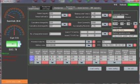
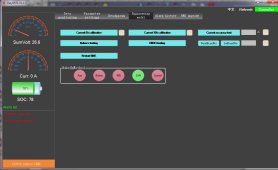
 . Done all the pre checks 1st of course and i spotted the Resistance was totally wrong.
Hope on hope i connected and tried all ways to boot it up - it eventually showed the cell voltages, but then that disappeared.
Tried reprogramming the voltages to the correct settings but no joy either. They are a pain in the neck when not firing up.
Have started another "Refund please". I used AliExpress. Will's fav store ???
I do have one that worked straight out of the box, easy peasy, and has not let me down so far after 3 month.