diy solar

diy solar

Need to bond neutral + ground for off grid shed using PIP 3048LV-MK 48V 3kW 120V Inverter

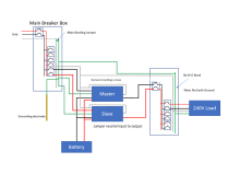
First, this is my understanding of the MPP units:

View attachment 84508


The PIP 3048LV-MK may be different but I seriously doubt it.

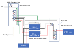
Assuming the PIP 3048LV-MK is the same, this is what it will look like in your set up.

View attachment 84509
Notice that when the inverter is on battery, the bonding relay creates an N-G bond. Since there should always be one, but only one N-G bond, the breaker box should keep the neutral and ground separate.

However, when the inverter is on AC-input (Pass-through) the Bonding relay removes the N-G bond. It is expecting the input to provide the bond.

Most small gasoline generators in the US do not provide an N-G bond so you have a few choices.
1) On some generators it is possible to open them up and connect the neutral and ground.
2) On generators that have multiple plugs on them, some people will plug this into an unused plug to create an N-G bond:
This works well, but you have to remember to use it.
3) You can create a bond by putting a jumper between the AC input Neutral and Ground terminals. (THis can be a PITA because the terminals are typically not large enough for two full size wires.
4) You can make a 'pigtale' with an N-G bond. (This is essentially a short extension cord that has an N-G bond in one of the connectors. )
5) You can build an NG-bond into the extension cord between the generator and inverter.... but make sure not to use that cord elsewhere.

Note: If you are not familiar with the purpose and importance of the N-G bond, you may want to review these grounding tutorials:

On an existing set-up,

The easiest way to check for the existence of an N-G bond is to check for voltage between neutral and ground. If there is little or no voltage, there is almost certainly an N-G bond someplace on the circuit. (It is best to do this when NOT under load) Since an inverter may dynamically create the NG bond, this should be tested when power is from the batteries and again when power is from the AC-IN.

The easy way to detect multiple N-G bonds is to look for current on the ground wire between the two possible N-G bonds while under load. If there are two N-G bonds, then the ground becomes a parallel conductor to the neutral and will carry ~ 1/2 the current.

View attachment 84574
thank you so much for this!
 
The LV6548 is a separately derived system when in battery mode because it bonds the neutral and ground (the same as a generator that has neutral and ground bonded). Therefore, the neutral has to be switched, which the LV6548 does. But because both inverters bond the neutral and ground, objectionable current flows on the ground.

It also looks like it has a removeable bonding screw.


Removing the screw would make the LV6548 a non-separately derived system when in battery mode and it could then be treated the same as a generator that does not have neutral and ground bonded. The grid neutral and the inverter neutrals could then be connected even while the inverter is in battery mode. The problem of multiple neutral ground bonds is eliminated because the only neutral-ground bond is in the main panel.

That still leaves the problem of multiple neutral paths. I think those can be eliminated by connecting the main panel neutral to the inverters only on the inverter inputs and jumpering the inverter neutral inputs to their outputs.

I have not tried this and it is probably not supported by the manufacturer, so use at your own risk.

inverter 2.png
 
I have a large system that I have recently built it. https://diysolarforum.com/threads/m...e-304ah-lifepo4-battery-14-kw-pv-array.32343/ If you wire it the way this schematic shows with no output ground you take away its capability to operate the way it is designed to. The key is to have no neutral ground bonding on the load side of ether source Main panel in bypass or Inverter when it is the sole source of electric. This unit is not a grid assisted type it is either bypass or separately derived.
 
I have not tried this and it is probably not supported by the manufacturer, so use at your own risk.
MPP support specifically said it is not supported to connect Neutral-In and Neutral-out.

I have often wondered if it would work or not (independent of support or not). I have not tried it either, but I suspect that if it did not work we would have heard reports of it.

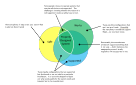
We have a situation where we must figure out the intersection of what works, what is supported, and what is safe.

1646241625581.png
 
MPP support specifically said it is not supported to connect Neutral-In and Neutral-out.

I have often wondered if it would work or not (independent of support or not). I have not tried it either, but I suspect that if it did not work we would have heard reports of it.

We have a situation where we must figure out the intersection of what works, what is supported, and what is safe.

View attachment 85823
I agree but if you follow the manufacturer supplied wiring diagrams for connecting two or more inverters, you will end up with objectionable current and multiple neutral paths so what do you do?
 
The two units work in concert with one anther the are either both in bypass or not the system sees them as one unit. I hope this does not come across as adversarial comments . It is hard to convey these conversations in text with no tone. I apricate that most commenters are trying to come to the safest conclusion.
 
The two units work in concert with one anther the are either both in bypass or not the system sees them as one unit. I hope this does not come across as adversarial comments . It is hard to convey these conversations in text with no tone. I apricate that most commenters are trying to come to the safest conclusion.
I would also add that because of all the discussion that has taken place I am currently changing out my 2 pole transfer switch out to a 3 pole to eliminate the neutral connection on the load side of both sources that causes the objectionable current.
 
It doesn't come across as adversarial at all. Please post your new wiring diagram with the 3-pole transfer switch.
 
I agree but if you follow the manufacturer supplied wiring diagrams for connecting two or more inverters, you will end up with objectionable current and multiple neutral paths so what do you do?
You point out a case where there are supported configurations that aren't safe.:(

What is worse is that MPP (and Growatt) don't even document the behaviors well enough to figure out how to do it safely.
 
Last edited:
I have not tried this and it is probably not supported by the manufacturer, so use at your own risk.
BTW: The configuration you show (Repeated below) is supported by Growatt on their older 3K models that don't have the internal bonding relay. I do not know if it is supported on the newer models.

1646251361218.png


The Growatt and MPP inverter designs appear to be very similar. Even the user interface is similar. I suspect they both started from the same designs. MPP changed the design to include an internal bonding relay a couple of years ago. Growatt changed their units to have an internal bonding relay much more recently. (Some shipping Growatt units still appear to be the old design)
 
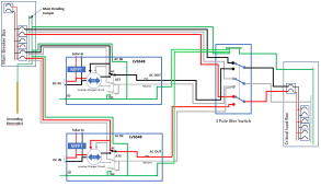
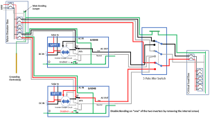
This is the way I am wiring my system. It would never have the neutral and ECG bonded at more than one point at any given time. Since the two inverters communicating the way they are designed will both either be in bypass or inverting at the same time the system will only see one source.LV6548 with 3pole transfer switch.png
 
BTW: The configuration you show (Repeated below) is supported by Growatt on their older 3K models that don't have the internal bonding relay. I do not know if it is supported on the newer models.

View attachment 85845


The Growatt and MPP inverter designs appear to be very similar. Even the user interface is similar. I suspect they both started from the same designs. MPP changed the design to include an internal bonding relay a couple of years ago. Growatt changed their units to have an internal bonding relay much more recently. (Some shipping Growatt units still appear to be the old design)
Interesting. So if they would do a firmware change that allowed the choice of bonding or not (or even said it's OK to remove a screw), we would have a solution that is both safe, supported, and works (the magic intersection).

The video I mentioned earlier, around 5:32 lower left, shows what may be a bonding screw with a image next to it possibly showing the screw removed as if that is something permissible. I don't think that is the screw that was removed in the video.

 
This is the way I am wiring my system. It would never have the neutral and ECG bonded at more than one point at any given time. Since the two inverters communicating the way they are designed will both either be in bypass or inverting at the same time the system will only see one source.View attachment 85848
Three potential issues with this layout.

1) When in 'invert' mode (powered by the battery) Both inverters will have an N-G bond. There is a screw inside the LV6548 that will disable the bonding relay. This screw should be removed on *one* and only one of the inverters.

2) By having both the Input and output grounds tied together, there are big ground loops that can cause RFI issues, particularly when the inverters are in invert mode. The output grounds should be disconnected.

3) Since the output grounds are tied together at the xfer switch, there is a big loop in neutral when the inverters are in pass-through mode.
This has the potential for RFI issues. (At least the loop does not exist when the inverters are in invert mode and generating a lot of noise)
To fix this potential problem, you would need to use a 4 pole transfer switch.

EDIT/UPDATE: My idea of using a 4 pole switch does not really fix the problem if the inverter is in pass-through and the xfer switch is on inverter. You might as well use a 3pole switch. I do not know a way of eliminating the loop on neutral.

The resulting system would look like this: (Edited picture to reflect the above correction)
1646256348768.png
 
Last edited:
Interesting. So if they would do a firmware change that allowed the choice of bonding or not (or even said it's OK to remove a screw), we would have a solution that is both safe, supported, and works (the magic intersection).
On this thread a poster indicated MPP solar said that removing the screw would safely disable the bonding:

 
Three potential issues with this layout.

1) When in 'invert' mode (powered by the battery) Both inverters will have an N-G bond. There is a screw inside the LV6548 that will disable the bonding relay. This screw should be removed on *one* and only one of the inverters.

2) By having both the Input and output grounds tied together, there are big ground loops that can cause RFI issues, particularly when the inverters are in invert mode. The output grounds should be disconnected.

3) Since the output grounds are tied together at the xfer switch, there is a big loop in neutral when the inverters are in pass-through mode.
This has the potential for RFI issues. (At least the loop does not exist when the inverters are in invert mode and generating a lot of noise)
To fix this potential problem, you would need to use a 4 pole transfer switch.

The resulting system would look like this:
View attachment 85853
Note: In the diagrams above, I indicate removing the screw interrupts the ground connection to the bonding relay. It could just as easily interrupt the neutral connection to the bonding relay. (I do not think it interrupts the control to the relay because when the power is off, the bonding is present. This implies the bond is created on the 'normally closed' side of the relay and disconnecting the control would leave things permanently bonded)
 
Three potential issues with this layout.

1) When in 'invert' mode (powered by the battery) Both inverters will have an N-G bond. There is a screw inside the LV6548 that will disable the bonding relay. This screw should be removed on *one* and only one of the inverters.

2) By having both the Input and output grounds tied together, there are big ground loops that can cause RFI issues, particularly when the inverters are in invert mode. The output grounds should be disconnected.

3) Since the output grounds are tied together at the xfer switch, there is a big loop in neutral when the inverters are in pass-through mode.
This has the potential for RFI issues. (At least the loop does not exist when the inverters are in invert mode and generating a lot of noise)
To fix this potential problem, you would need to use a 4 pole transfer switch.

The resulting system would look like this:
View attachment 85853

With the 4 pole transfer switch in the inverter position and the inverters in bypass mode, I think there would still be multiple neutral paths because the neutral current for a 120V load would be able to return to the grid through both inverters.
 
With the 4 pole transfer switch in the inverter position and the inverters in bypass mode, I think there would still be multiple neutral paths because the neutral current for a 120V load would be able to return to the grid through both inverters.
Well Shit..... I am feeling pretty stupid now. You are right. The 4 pole switch does not really help. I don't know how I missed that.
 
Excellent! Looks like the issue is solved at least for the LV6548.
I may be wrong here but without that screw in place the inverters will not be able to see a ground fault in inverting mode because you have removed the only place they are capable of bonding when they are the source of power. The breaker at the main panel will not clear a fault since the relays have disconnected from that source.
 
Back
Top