diy solar

diy solar

Signature Solar's new EG4 6000 120/240V inverter

[what I don't know for sure is whether the input neutral is connected to the output neutral (and center tap) when in pass-through mode.

Let's assume the inverter does connect the input and output neutrals in passthrough mode. In this case, the output transformer would act as an autotransformer with the neutral from the grid tied to the center tap of the output transformer. In this situation, at least some of the neutral current from the 120V load would be handled by the autotransformer (But I don't know how much). If the input neutral is completely disconnected, the transformer would act as an auto-transformer and handle all the neutral current of the 120V load.
What about measuring resistance between the unit neutral and the output neutral while in passthrough mode running a decent sized load?

That would tell us if those two are latched by a relay, because they are not connected otherwise based upon my other tests.
 
What about measuring resistance between the unit neutral and the output neutral while in passthrough mode running a decent sized load?

That would tell us if those two are latched by a relay, because they are not connected otherwise based upon my other tests.
and voltage reading between IN-OUT neutrals for the two operating mode ? I had to remove a bonding screw on my MPP hybrid inverter circuit board. SignatureSolar knows all about these bonding issues.
 
What about measuring resistance between the unit neutral and the output neutral while in passthrough mode running a decent sized load?

That would tell us if those two are latched by a relay, because they are not connected otherwise based upon my other tests.
Measuring resistance on a live system is not something I would attempt.... Even if it doesn't blow out the ohm meter, it is not clear if the reading would be correct.
 
Measuring resistance on a live system is not something I would attempt.... Even if it doesn't blow out the ohm meter, it is not clear if the reading would be correct.
agree, but measuring AC voltage should work
 
agree, but measuring AC voltage should work
I guess we could try voltage. Measure the following

1) Neutral in to neutral out when under the battery (but AC is on)
2) Neutral in to Neutral out when in pass through.

The concern I have is that in both cases the bonding to ground is going to keep the voltage to near zero.
 
Last edited:
perhaps the solution is simply leave input AC-Neutral unconnected. The output AC-Neutral will run to the main panel where it's bonded to earth ground, and at just one point, no ground loop current; pass-through or battery-mode.
 
So I went back and read some of the earlier posts.
So with all grounds (aka green wire, aka bare wire) disconnected everywhere and the inverters disconnected from solar and the batteries (I have no grid input during testing), the inverters still showed zero resistance across the neutral and ground terminals. Just in case there was a magic relay in the system somewhere, I also tested with the inverter running when there was only solar input, and also when there was solar input and AC output. Neutral and ground are connected in all operational scenarios.
I don't trust resistance readings if a system is powered. The voltage present can easily screw up the measurement.

1) If the inverter is powered on, the best way to check for bonding is to check voltage from neutral-out to ground with no load on the inverter. If you see anything more than a volt or two, it is floating (no bond). This check should be done when the inverter is in pass-through and again when under inverter mode.

Case 1.1 Voltage found between Neutral-out and ground in both modes.
- There is no bond being generated by the inverter at any time
- The input neutral-in is not being connected to neutral-out in passthrough mode.

Case 1.2 Voltage Voltage between Neutral-out and ground in inverter mode but not in passthrough mode.
- There is no bond being generated by the inverter
- The neutral-in and neutral out is being connected in Pass-through mode.

Case 1.3 No voltage between neutral-out and ground in both modes.
- We can not tell much. There could be dynamic bonding or there could no neutral switching and a permanent bond.

2) If the inverter is totally disconnected from any power source (including the ground wires)

Case 2.1: There is no resistance between output neutral and ground,
- we know there is some kind of binding done by the inverter.... but we do not know if it is a dynamic bond or a permanent bond. (This is the same as case 3 above.

Case 2.2: There is high resistance between output neutral and ground.
- There is probably no dynamic bonding. (All inverters I am aware of that do dynamic bonding have the bond enabled when powered off)
- There is no permanent bond created by the inverter.

Case 2.3 There is no resistance between output neutral and input neutral
- The system probably has a common neutral.

Case 2.4 There is high resistance between output neutral and input neutral
- The system does not have a common neutral but may connect neutral in and neutral out in passthrough mode
 
I have 2 of the 6000EX’s for a complete off grid shop. The AC output of the inverters I’m running to a panel. Do I need to bond neutral and ground in the panel?

Also just checking but each inverter needs a double pull 40amp breaker so a total of 4 spots will be taken at the panel?

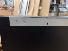
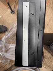
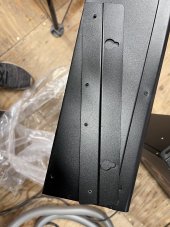
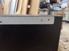
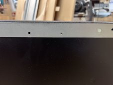
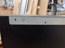
Also did any one else not have their mounting brackets broken off when they opened the inverters? 5F932FC9-E475-46F3-8FFF-4DE3214C283A.jpeg
 

Attachments

  • DBE4765F-86D8-49C5-93AA-4751D754C214.jpeg
    DBE4765F-86D8-49C5-93AA-4751D754C214.jpeg
    191.3 KB · Views: 13
  • 68EAE6BB-4F6F-4A42-B306-2FF3F3F80079.jpeg
    68EAE6BB-4F6F-4A42-B306-2FF3F3F80079.jpeg
    239.4 KB · Views: 14
  • C0CBD6C7-5A80-42DC-9008-8FF7B198BD6D.jpeg
    C0CBD6C7-5A80-42DC-9008-8FF7B198BD6D.jpeg
    186.1 KB · Views: 14
  • 4248CCC2-275D-49D5-8C68-792E167A5D51.jpeg
    4248CCC2-275D-49D5-8C68-792E167A5D51.jpeg
    199.4 KB · Views: 14
  • 25BBC3DC-6CA3-401C-A774-26B667B14358.jpeg
    25BBC3DC-6CA3-401C-A774-26B667B14358.jpeg
    193.1 KB · Views: 13
I am NOT an expert, just my speculation.

I think it is wrong to put power in on breaker panel breakers that normally are where you attach power out, in the same breaker box where you have breakers that send power out to loads.

In my opinion, I would think it would be safer to dedicate a small breaker distribution panel for all incoming breakers to bring in all paralleled breakers, then the main breaker on that box, becomes an outgoing Main Breaker - which is then connected to a second breaker panel’s Main input breaker, to be distributed to all outgoing breaker loads.

So all paralleled inverter power sources are combined in a breaker box dedicated to only combining incoming power.

Then the Main from the AC Combiner Breaker Panel is then wired to the Distribution Breaker Panel’s Main breaker (just as if it was coming from the grid).

Any feedback on this idea?

If you like this concept, the next question is where to apply the ground neutral bond?

I speculate it should be in the Distribution Breaker Panel????
Also I think the neutral from Combiner to Distribution panel, should be disconnected when the Combiner to Distribution breaker(s) are switched off???
 
@Marqese - Do not bond the Neutral in your subpanel. The only place the Neutral and ground should be bonded are in the main service panel. After that the neutral and the ground are separate wires and should not be connected again.
 
@Marqese - Do not bond the Neutral in your subpanel. The only place the Neutral and ground should be bonded are in the main service panel. After that the neutral and the ground are separate wires and should not be connected again.
hey so this is a complete off grid system so there is no main service panel.
 
I have 2 of the 6000EX’s for a complete off grid shop. The AC output of the inverters I’m running to a panel. Do I need to bond neutral and ground in the panel?

Also just checking but each inverter needs a double pull 40amp breaker so a total of 4 spots will be taken at the panel?

Also did any one else not have their mounting brackets broken off when they opened the inverters? View attachment 113491
Also please post photos of your install, as you
@Marqese - Do not bond the Neutral in your subpanel. The only place the Neutral and ground should be bonded are in the main service panel. After that the neutral and the ground are separate wires and should not be connected again.
But I am not considering the Distribution Panel as a Sub Panel, I consider it to be the Main Service Panel.

The AC Combiner Panel I consider as equivalent to incoming Grid Source from a grounding point of view???
 
I am NOT an expert, just my speculation.

I think it is wrong to put power in on breaker panel breakers that normally are where you attach power out, in the same breaker box where you have breakers that send power out to loads.

In my opinion, I would think it would be safer to dedicate a small breaker distribution panel for all incoming breakers to bring in all paralleled breakers, then the main breaker on that box, becomes an outgoing Main Breaker - which is then connected to a second breaker panel’s Main input breaker, to be distributed to all outgoing breaker loads.

So all paralleled inverter power sources are combined in a breaker box dedicated to only combining incoming power.

Then the Main from the AC Combiner Breaker Panel is then wired to the Distribution Breaker Panel’s Main breaker (just as if it was coming from the grid).

Any feedback on this idea?

If you like this concept, the next question is where to apply the ground neutral bond?

I speculate it should be in the Distribution Breaker Panel????
So the plan was put the inverter input breakers on one side and the load breakers on the other side. What should I look out for?
 
So the plan was put the inverter input breakers on one side and the load breakers on the other side. What should I look out for?
I am not knowledgable to offer a safe answer to that question. I am learning, at the same time, and do not have access to the hardware for testing. But intend to build a system similar to yours, with eg4 6000exs in parallel, and eg4-LL v2 in parallel.

There are so many unknowns that I am seeking as much knowledge as possible, so I dont damage the equipment, or myself.

Please post photos as you proceed with your installation so we all can visualize the process for our own designs.

thx
 
hey so this is a complete off grid system so there is no main service panel.
In that case, one of the EG4s becomes your first piece of service equipment and should be bonded. Your ground rod connection comes to that EG4 as well. After that, N and G stay separate, including in your sub panel.
 
In that case, one of the EG4s becomes your first piece of service equipment and should be bonded. Your ground rod connection comes to that EG4 as well. After that, N and G stay separate, including in your sub panel.
Again I am not experience, this is merely my speculation:

If we think of the inverters “as if” they were the source from grid, the grid grounds at the power pole that feeds the house, then the first Service Distribution panel, the electrician creates a neutral ground bond.

So in this scenario, I would think it is reasonable to have a single ground for the Power Generation equipment (just as if it was coming from the power pole as it would be if it were from the grid),
and a second separate ground neutral bond in the Service Panel, as would be in a grid tied service panel.

Please advise???
 
Seems like I should be able to just remove the bonding screws in the inverters and bond N and G in the panel?
 
Seems like I should be able to just remove the bonding screws in the inverters and bond N and G in the panel?
If you never hook the grid to the input that is true. However if you hook the grid to the input, then in pass-through mode there will be two N-G bonds..... that is a no-no.
 
Back
Top