Of course this is not normal but wont help you.This is reactive power, which is normal.


You are using an out of date browser. It may not display this or other websites correctly.
You should upgrade or use an alternative browser.
You should upgrade or use an alternative browser.
Deye 5k Hybrid zero export to ct issue
- Thread starter torstein
- Start date
yea so i just have to live with this as a minimal usage? gues it could help to move as much over to the critical side?Of course this is not normal but wont help you.
pilotdrh
New Member
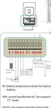
Just wondering why your CT is connected to 3 and 4 instead of 5 and 6.
Says so in the manual?Just wondering why your CT is connected to 3 and 4 instead of 5 and 6.
Attachments
pilotdrh
New Member
What is the model number of your Deye?
What is the model number of your Deye?
SUN-3.6/5/6K-SG03LP1-EU | 3.6-6KW | Single Phase | 2 MPPT | Hybrid Inverter | Low Voltage Battery Inverter Company, Supplier | Deye Inverter Technology
NingBo Deye Inverter Technology Co.,Ltd is China SUN-3.6/5/6K-SG03LP1-EU | 3.6-6KW | Single Phase | 2 MPPT | Hybrid Inverter | Low Voltage Battery inverter company and supplier。 SUN 3.6/6K-SG,hybrid inverter, is suitable for residential and light commercial use, maximizing self-consumpti...
pilotdrh
New Member
I had a look at the manual, didn't see anything. I have seen on the Sunsynk that they specifically mention using the same kind of wire as on the CT to extend it. These CTs have a very low output, the systems I worked on all use CTs with a 5 amp secondary. Years ago a lot of stuff used a 1 amp. My 16 kW has a 300A/150mA CT. At my rated pass through of 100 amps it would only output 50ma. Wire size, type and resistance is critical at these levels.
Attachments
Yes. Its strange. I think i have had some bad ground earlier to the inverters. Not surere if it was it or something Else strange. But now my ct consumption is 120w i stead of 360w. So its better today.I had a look at the manual, didn't see anything. I have seen on the Sunsynk that they specifically mention using the same kind of wire as on the CT to extend it. These CTs have a very low output, the systems I worked on all use CTs with a 5 amp secondary. Years ago a lot of stuff used a 1 amp. My 16 kW has a 300A/150mA CT. At my rated pass through of 100 amps it would only output 50ma. Wire size, type and resistance is critical at these levels.
pilotdrh
New Member
Grounding issues can cause weird symptoms.
I have some issue with the CT reading as well, and it seems to be multiple issue could be in the game. The cable to the CT extended with a shielded CAT6 cable, approximately 17-18m. When I connected to the inverter, as per the manual suggested, I had a reading of 20W at any point when had import or export to the grid. Then I came across with another manual, which suggested to connect the CT differently. I tried then I had a very close reading to the realistic load, I tried with a kettle, a heat gun within 100W. At the moment I have the CT connected to 5 and 6. The other issue with the DEYE Icloud. Seems to be the inverter stops sending data at 8pm until 8 am. I tried to figure out if there is any setting what I missed but not much luck. Any suggestion?


pilotdrh
New Member
Check this out.
Will try this. Just need to fully understand what he is doing firstCheck this out.
")
I think you need 2 ct sensors if you have setup in 3phase paralell. If not we do not use 5 and 6. I have tested this and they work the same as far as i know.I have some issue with the CT reading as well, and it seems to be multiple issue could be in the game. The cable to the CT extended with a shielded CAT6 cable, approximately 17-18m. When I connected to the inverter, as per the manual suggested, I had a reading of 20W at any point when had import or export to the grid. Then I came across with another manual, which suggested to connect the CT differently. I tried then I had a very close reading to the realistic load, I tried with a kettle, a heat gun within 100W. At the moment I have the CT connected to 5 and 6. The other issue with the DEYE Icloud. Seems to be the inverter stops sending data at 8pm until 8 am. I tried to figure out if there is any setting what I missed but not much luck. Any suggestion?
View attachment 114959
View attachment 114960
Elexide
New Member
I thought it doesn't matter unless you have grid sell enabledI get my reading from solar assistant that get the info from the inverter.
Maybe When setting max sell 200w its only selling 200w.change this to zero unless you want to sell back.
edit,
Just checked this setting on mine and it is at 5000W,
but zero export.
pilotdrh
New Member
I think you need 2 ct sensors if you have setup in 3phase paralell. If not we do not use 5 and 6. I have tested this and they work the same as far as i know.

This is what my Single phase 16 kW manual shows. 2 Ct's for split phase. 1 CT for single phase.

pilotdrh
New Member
We used to use something like this for cross current circuits on generators. Back in the day when we used CT's with a 1A secondary the CRT would be wired to the voltage regulator and a small circuit board that was basically a step up transfomer. Each gen would have the same setup. The xformer would have 120 VAC on the secondary. All of the xformer secondaries would be wired in series, a big loop. When 1 gen had more or less current than the others the loop was designed so that the currents would cancel out, the one(s) that were left with a higher or lower current would then cause the VR to raise or lower it's voltage. Gens with a 5 amp CT did not need this, they were wired directly between the gens in a loop.Will try this. Just need to fully understand what he is doing first
So in the scheme shown on the vid he is providing more power for the wire run with the first CT and then using the 2nd to drop the current level back to what the Inv CT is looking for.
pilotdrh
New Member
The CT signal is what the inverter monitors to control how much power it is producing on the grid connection. Even if you do not have sell enabled it uses it so it doesn't push back power to the grid. Depending on your grid and what kind of loads are in your neighborhood the grid can fluctuate. Not so much in frequency but in voltage. So instead of producing/consuming active power (kW controlled by frequency) you can also produce/consume reactive power (amps controlled by voltage). This is reflected by your power factor, PF. The specs say 0.8 leading to 0.8 lagging, capacitive load vs inductive load. It would be nice if the manual went into more detail for stuff like this. You can find you PF setting under Grid Setting.I thought it doesn't matter unless you have grid sell enabled
pilotdrh
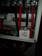
New Member
My setup is easy, whole house, no load on the grid side. So I put my CT right on the L1 cable inside my inverter, plenty of room.The CT signal is what the inverter monitors to control how much power it is producing on the grid connection. Even if you do not have sell enabled it uses it so it doesn't push back power to the grid. Depending on your grid and what kind of loads are in your neighborhood the grid can fluctuate. Not so much in frequency but in voltage. So instead of producing/consuming active power (kW controlled by frequency) you can also produce/consume reactive power (amps controlled by voltage). This is reflected by your power factor, PF. The specs say 0.8 leading to 0.8 lagging, capacitive load vs inductive load. It would be nice if the manual went into more detail for stuff like this. You can find you PF setting under Grid Setting.
Attachments

Elexide
New Member
The CT signal is what the inverter monitors to control how much power it is producing on the grid connection. Even if you do not have sell enabled it uses it so it doesn't push back power to the grid. Depending on your grid and what kind of loads are in your neighborhood the grid can fluctuate. Not so much in frequency but in voltage. So instead of producing/consuming active power (kW controlled by frequency) you can also produce/consume reactive power (amps controlled by voltage). This is reflected by your power factor, PF. The specs say 0.8 leading to 0.8 lagging, capacitive load vs inductive load. It would be nice if the manual went into more detail for stuff like this. You can find you PF setting under Grid Setti
Right , misundertood you earlier then read the rest of your post . My bad, thought you were saying the sell value needs to be set to zero to avoid selling back to the grid as opposed to just turning export off and letting the value be whatever it is by default.My setup is easy, whole house, no load on the grid side. So I put my CT right on the L1 cable inside my inverter, plenty of room.
Similar threads
- Replies
- 26
- Views
- 2K
- Replies
- 7
- Views
- 407
- Replies
- 5
- Views
- 921
- Replies
- 2
- Views
- 539