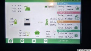
Yes CTs are installed on the "Lines" in the 18kpv cabinet? Even though i have the arrows pointing to the inverter, i still had to set reverse to get any data to show.
Setup:
main panel with 60 amp feeding the EG4 18kpv inverter. Main panel is 200A and 200A buss bar (cannot backfeed, unless you know a way without overloading the buss). Inverter has 3650W of solar, 1 EG4 PowerPro battery (additional on the way) and grid. Output goes to 125A "critical load" panel.
Offgrid output - On
CT direction reversed - On
Seamless switch - On
Charge Last - Off
RSD disable - On
PV Arc - On
Zero export - On
Backup EPS enabled
Off-grid mode disabled
AC Charge:
AC charge enable
stop AC charge SOC 100%
last charge disable
battery priority disable
Discharge:
on-grid cut-off SOC 10%
off-grid cut-off SOC 0%
Forced discharge enable
stop discharge SOC 10%
I have to disable Forced Discharge and enable AC Charge and set a time of 00:00 - 23:59 and it will start changing
I then have to disable AC Charge and enable Forced Charge and set a time to 00:00 - 23:59 and it will start discharging.
If I leave it on AC charge, it will never discharge and use solar or grid instead. Same for discharge. if i leave that on, it will stop at 10% and AC charge will never start charging from solar or grid.
Do I have the CTs in the right place? Manual shows them on the feed from the main panel. Do i need to have them on the main lugs of the main panel? Why would the flow have to be reversed?