diy solar

diy solar

New Daly "Smart" BMS w/ Communication. (80-250A)

The SOC problem has already solved. After changing rated capacity you have to reset the BMS in the engineering menu in the program.
About unstable current measurement when an inverter is working - I think there is only one good way to solve it. It is program averaging inside the BMS. It needs firmware update.
 
You would need 2 back to back, but yeah, main problem is leakage. That's why I linked a ceramic one: https://www.mouser.fr/ProductDetail/Taiyo-Yuden/AMK316ABJ107ML-T?qs=sGAEpiMZZMsh%2B1woXyUXj%2BamvhD7guHr8XarkzKCfqU=
Very nice cap: 100 uF, 4V, ceramic
Size: 3.2 x 1.6 mm
Is the body large enough to attach wires to the ends? Or do you need to solder the cap to a circuit board? Guess I’ll find out as the parts will be ordered.

I’m not concerned with the slower response time (if multi stages are required).
 
Yea, MLCCs have gone a long way, you can have pretty big capacities if you don't need a somewhat high voltage cap. I checked and the less expensive TH one is around 10 $ so that's why I linked a SMD one.

It's a 1206 part so not too small, you can solder wires to it without too much trouble if you want. I recommend tweezers and tinning the wires beforehand.

The simplest without a PCB would be to solder it to the inductor, solder some wires to them and put heatshrink tubing over the thing ;)
 
  • Like
Reactions: Cal
Almost a thread for the "danger zone" guys!!

My basic knowledge of electronics makes it hard to follow the Wizards.

Daly normally have really good aftersales service.
(But crappy manual writers)

If I understood correctly the main problem is that the BMS provide wrong information about charge, discharge and SOC (who are all somewhat related)

Or am I missing something?

If this is still the main issue, they should be able to fix!

It’s likely the Daly is getting the correct current measurement. However due to the sinusodal ripple current when using an inverter, there’s a chance measurements are skewed towards the peak or trough of the ripple. A software mod will not fix an alias problem. In addition, the displayed current on your monitor will constantly change, depending on the point in time the measurement is made in relation to the ripple voltage. A filter at the shunt is a good fix.
 
I'm hoping I don't regret this but it's done
 

Attachments

  • Screenshot_20200715-192837.jpg
    Screenshot_20200715-192837.jpg
    81.4 KB · Views: 118
It’s likely the Daly is getting the correct current measurement. However due to the sinusodal ripple current when using an inverter, there’s a chance measurements are skewed towards the peak or trough of the ripple. A software mod will not fix an alias problem. In addition, the displayed current on your monitor will constantly change, depending on the point in time the measurement is made in relation to the ripple voltage. A filter at the shunt is a good fix.
Hey @Cal did you try out your filter yet? In the Chargery thread I had said I was going to try a simple RC filter, 10k and 2.2uF, 7Hz. I never did try it as I am now using the Electrodacus SBMS0 which does not exhibit this aliasing artifact. I looked at the schematic and guess what? It has a current sense amplifier followed by simple RC filter with 1k and 22uF, then ADC. Same 7Hz corner but different values. It seems to work well, no current measurement problems when I run my inverter.

As to the measurements skewing to peak or trough... at least for the Chargery what I saw was an aliased artifact with a large approximately sinusoidal variation and a period of about 7 seconds. I think any current measurements it takes will have the same distribution as the 120Hz ripple itself, just mixed down to near DC. Although depending on how close the ADC sample frequency is to a multiple of 120Hz, it could mix all the way down to DC or at least a very low frequency with even longer period than 7 seconds.
 
Thanks, interesting info. Looks like the Electrodacus got it right.

But no, haven’t tried the filter. I’m in the Gorge since mid June. Don’t expect to get home till mid August. Some time in September I’ll try it.
 
Hi, new here - thought I'd share my experience with this smart box.
I ordered and received daly 60amp smart bms +bluetooth +uart usb cable. All arrived fine.
In the box: wiring diagram, BMS, spaghetti cable, temp sensor, bluetooth, uart cable and some "on-off" switch.

Had to figure out how to initialise it, apparently, the right sequence is connect everything, then switch to On, then short P- and B-. If the temp sensor is not connected - it won't come up, which is not handy really - I don't need it as we don't have subzero temps here.
I've received a 4S x 150A LiFePo4 Smart BMS and a 16S x 250A LiFePo4 with Bluetooth and UART cables. I am trying to get them working with IPhone AP and UART/PC SW.

- 4S BMS works with the Bluetooth dongle (4-pin JST) and IPhone Ap that appears to be a different one than you are referencing; maybe they have updated this? The Ap only reports data and the parameter setting functions do not seem to work.
- 4S BMS does not work with UART connection to PC. Similar to you, serial connection is confirmed but no data transferred either way. I am using PC SW from download link (not 'new' SW you referred to).

- 16S BMS has 6-pin JST for UART/BT/GPS and I received 4-pin JST cable on Bluetooth dongle so cannot connect. Nothing to report yet.

Have you sorted out your system yet? Are there new SW and APs available somewhere? Thanks.
 
For the BT, I might be to help.

They probably shipped a wrong BT connection.

I checked my 6 pin, 4 wire Bluetooth.
It's straight forward, the middle 2 are not used. Nothing twisted or strange.

If you split the 4 cable in 2 pairs, the 2 on the left go left, the 2 on the right go right
You probably can cut the JST into half.

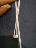
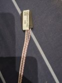
IMG_20200811_105014_copy_750x1000.jpgIMG_20200811_105023_copy_750x1000.jpg

Naturally, not the best solution, it will make it work fast.
Alternatively you can return the BT to the seller and receive one with right JST.
 
For the BT, I might be to help.

They probably shipped a wrong BT connection.

I checked my 6 pin, 4 wire Bluetooth.
It's straight forward, the middle 2 are not used. Nothing twisted or strange.

If you split the 4 cable in 2 pairs, the 2 on the left go left, the 2 on the right go right
You probably can cut the JST into half.

View attachment 19589View attachment 19590

Naturally, not the best solution, it will make it work fast.
Alternatively you can return the BT to the seller and receive one with right JST.
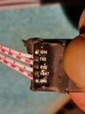
Thanks for looking into that for me. The 4-pin cable (for 4S Smart BMS) is not reversible, the way your 6-pin is. For some reason, the 4-pin BT port (GND, RX, TX, 3.3V) on the 4S BMS is not the same as the 6-pin port (GND, 3.3V, x, x, TX, RX) on the 16S BMS; so my cable can't be split, as you suggest, and connected. I have 6-pin JST connector ends here that I can install, I just needed to confirm the pin-out for that port. Thanks for your help.
 
Hi, new here - thought I'd share my experience with this smart box.
I ordered and received daly 60amp smart bms +bluetooth +uart usb cable. All arrived fine.
In the box: wiring diagram, BMS, spaghetti cable, temp sensor, bluetooth, uart cable and some "on-off" switch.

Had to figure out how to initialise it, apparently, the right sequence is connect everything, then switch to On, then short P- and B-. If the temp sensor is not connected - it won't come up, which is not handy really - I don't need it as we don't have subzero temps here.

The Bluetooth connection. Well, firstly the app is hopeless - the "group" account heeds to be created by the Ali store support, the individual account wouldn't work even if you're ready to share your phone number - the app will tell you the number format is not correct. Secondly and most importantly, only once I made it work on my tablet and spare phone after a hundred of unsuccessful launches - it is simply not connecting to the BMS. Maybe it has something to do with the Android version - the manifest in the APK file states that it expects the Android at 8.1 at least. Bottom line - if you want it to work, you may need to spend more money on something more recent than just an old phone from the shelf.

The UART connection. Well, the software from the website dalyelec.cn does not work at all - connecting to the serial but no data. Took the store support few days to ship me a very outdated version on the prolific driver (and they failed in the end, I have managed to find it somewhere at the end of the day) - but it didn't change a thing. Few more days, and they send me some totally different software "Sinowealth BMS Tool" which suddenly worked. Makes me think this Daly box may be not totally Daly inside?

UART protocol. They are completely refusing to share the protocol. Perhaps they don't have it for that third party IC ? That is an important part for me as I wanted to feed the stats into my raspberry pi and store there for further processing. I will give it a go wit the document from this thread, should it not work - I tried serial sniffer and the protocol does not seem to be too complicated.

Overall the experience is quite frustrating I'd say. They initially told me that I would be able to reprogram voltages etc, then they told me "not via bluetooth, pc app only", then they told me "changes via pc app only and only 5s bms and higher, nothing whatsoever is possible for 4s". However, I seem to be able to change parameters on the PC software. They still failed to provide me with a manual, and they still can't explain what is the purpose of the switch :). At the end of the day, it seem to do most of its job and it is 10 times cheaper than Orion so I guess all good.
Where can I get the "Sinowealth BMS tool", trying to use SW, it sees serial port 3/6 but still trying to connect to see data from BMS
 
downloaded it, just gotta get com opened from uart to pc to view, need to know how he got it communicating, its all about uart usb sending info, BT works but only shows SOC and amp draw, so I know BMS is working, just need 4s cell V to show up. Mainly want it to OVER/UNDER cell V protection from BMS, so verifying what it is set at, asked them to set at 2.8-3.65, we'll see, still hackn thru SW Sinowealth and PC Master(shows "COMMn but not "UART' in available connections.
 
downloaded it, just gotta get com opened from uart to pc to view, need to know how he got it communicating, its all about uart usb sending info, BT works but only shows SOC and amp draw, so I know BMS is working, just need 4s cell V to show up. Mainly want it to OVER/UNDER cell V protection from BMS, so verifying what it is set at, asked them to set at 2.8-3.65, we'll see, still hackn thru SW Sinowealth and PC Master(shows "COMMn but not "UART' in available connections.
Where did you find it??
Please share!!
 
I'd love to understand if it can communicate with my Victron gear over CAN!
Forget it, it is not because it has a CAN-Bus it has support for the Victron and especially Daly's technic manuals are extremely poor translations. I gave up on them. Want to buy my Brand-new 20s 400A from me for half price. That one is never used. New in the box. My other 2 I blew up. Hate Daly. Read my new thread. Found much better than Daly. 100 times better isn't exaggerating.
 
Where did you find it??
Please share!!
USE GOOGLE TRANSLATE TO SEE ENGLISH, its like the PC master, I can connect thru serial port 3/6, but l need to connect thru USB via UART, so UART shows in box, GO TO POST #206 his name is "Ms820", only 3 posts under his member name. you had a post right above and below,
 
Last edited:
USE GOOGLE TRANSLATE TO SEE ENGLISH, its like the PC master, I can connect thru serial port 3/6, but l need to connect thru USB via UART, so UART shows in box, GO TO POST #206 his name is "Ms820", only 3 posts under his member name. you had a post right above and below,
 
Forget it, it is not because it has a CAN-Bus it has support for the Victron and especially Daly's technic manuals are extremely poor translations. I gave up on them. Want to buy my Brand-new 20s 400A from me for half price. That one is never used. New in the box. My other 2 I blew up. Hate Daly. Read my new thread. Found much better than Daly. 100 times better isn't exaggerating.
Did you look at the resource section?
Filterguy and I managed to get almost all there is about Daly's interpretation of the protocols.

Daly can program for free matching protocol, if you tell them before ordering.

After studying what the usage would be for my inverters...
Just show the BMS information in the screen of the inverter.
That's all.
It did totally nothing with the communication, nothing more than the display unit available with the BMS would provide.

Well... I don't need to spend the extra costs and time to see it there.

In fact I stopped with Daly, and now use DIYBMS from Stuart

That one has WiFi!!!
 

diy solar

diy solar
Back
Top