diy solar

diy solar

New 10kw NHX AIO From Watts247

One of them has to be ground, so your test isn't working. You might not be testing against the interface ground rail.

Mike C.
If it’s like @Hedges said and the data ground is different than the chassis ground, that would explain why I wasn’t getting continuity.

When I check voltage between pins 1 and 4 with positive probe on pin 1, I get +5v, which leads me to think that the Solar assistant image is correct and pin 1 is 5v and pin 4 is “ground”.
 
The inverter is two 5 KW 120 VAC inverters internally. There is no autotransformer.
So it is a 5KW per phase max. You can not load 6KW on one phase. And that means one can configure load panel accordingly. Realistically, one can derive 4.5KW or so per phase. Hard to get breakers to add up exactly to 5KW.

Still excellent.
 
So it is a 5KW per phase max. You can not load 6KW on one phase.
You can for a short period of time.

It is also possible it may allow more than 5 KW on a phase individually if the other is not as loaded since heat limits may apply.

And that means one can configure load panel accordingly.
You want even phases if you can.

Realistically, one can derive 4.5KW or so per phase. Hard to get breakers to add up exactly to 5KW.
Breaker rating and loads are only loosely related.

Mike C.
 
Update on connector:

The connectors I found do work and seem to be exactly the right physical fit.

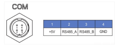
The pin out listed on Solar Assitant website is corerect:

1716591057225.png
Pin 1: +5 VDC
Pin 2: RS485 A
Pin 3: RS485 B
Pin 4: GND

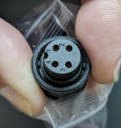
The picture shown on the Solar Assistant website is WRONG, however. The index mark is in the wrong place. The right pin out pattern is shown here:

1716591184812.png

I made an extender cable to move the Wifi module provided with the inverter so it would not be sealed up in a trough and it works fine.

Mike C.
 
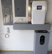
Here is my setup recently turned on:

1716591613474.png

I am having made a battery cover which will also double as a wall retainer. With this cover, I don't have to lift the battery onto the bracket EG4 provides and it allows me to disconnect and slide the battery forward out from under the trough.

I don't have a sola array yet, so it is just operating as a UPS system keeping the backup panel operating on grid failure. A grid down test resulted in no reset of any electronics device in the house.

Since the Amensolar inverter has Megarevo heritage, I configured the EG4 battery with CANbus Meagrevo protocol, told the inverter to use CANbus and lithium battery, plug in the cable, and it just worked. The battery comms seem to work, charging was controlled, battery SoC is displayed on the inverter, etc. When the inverter first boots, it takes about 20-30 seconds for the battery comm alarm to clear, but then it does and it all works.

Mike C.
 
That's a good looking install, glad to see someone is doing the AIO route in Indiana. Have you had any issues with permitting/inspections?
 
That's a good looking install, glad to see someone is doing the AIO route in Indiana. Have you had any issues with permitting/inspections?
The install is at my parent's house in Sarasota, FL. I am here for the week to do the install mins the roof part (mounts, rails, panels, etc). As it stands now, it is just a big UPS system but that will get them by in case of a power outage. A second EG4 battery will be added to it.

This is the work in progress:

1716605119368.png

Perhaps uniquely, we ran FMC inside the trough to keep the high voltage AC and DC circuits separate from the low voltage stuff. The PV wires run in FMC to the attic where a junction box will contain fuses, surge protection, and the RSD transmitter. The CTs are in the lower main panel and run through a flexible plastic conduit to the trough.

We did this work without permit so far but I am having PE stamped plans being drawn up. The permit is an issue because the AHJ wants a contractor listed and we can't find anyone willing to play so far. Our two possible strategies are to find at least an electrical contractor to work with us and be the contractor of record, or we have to operate under the "homeowner" exemption to do it ourselves. My mother is 83 yeas old, so presenting her as the contractor is perhaps a stretch. In Indiana, they will allow immediate family members to do this also, but there is no such rule here that I can find. We've even considered adding me to the deed to solve this issue. The permit/contractor issue is the biggest hurdle still to be overcome. We need to do this to make the system legal and to get net metering with the utility. We went ahead and did this much to give my parents backup power before the hurricane season starts.

We already have the panels, a pallet of 30 Canadian Solar CS6R-390MS-HL..

Mike C.
 
The install is at my parent's house in Sarasota, FL. I am here for the week to do the install mins the roof part (mounts, rails, panels, etc). As it stands now, it is just a big UPS system but that will get them by in case of a power outage. A second EG4 battery will be added to it.

This is the work in progress:

View attachment 217482

Perhaps uniquely, we ran FMC inside the trough to keep the high voltage AC and DC circuits separate from the low voltage stuff. The PV wires run in FMC to the attic where a junction box will contain fuses, surge protection, and the RSD transmitter. The CTs are in the lower main panel and run through a flexible plastic conduit to the trough.

We did this work without permit so far but I am having PE stamped plans being drawn up. The permit is an issue because the AHJ wants a contractor listed and we can't find anyone willing to play so far. Our two possible strategies are to find at least an electrical contractor to work with us and be the contractor of record, or we have to operate under the "homeowner" exemption to do it ourselves. My mother is 83 yeas old, so presenting her as the contractor is perhaps a stretch. In Indiana, they will allow immediate family members to do this also, but there is no such rule here that I can find. We've even considered adding me to the deed to solve this issue. The permit/contractor issue is the biggest hurdle still to be overcome. We need to do this to make the system legal and to get net metering with the utility. We went ahead and did this much to give my parents backup power before the hurricane season starts.

We already have the panels, a pallet of 30 Canadian Solar CS6R-390MS-HL..

Mike C.
Looks great!
 
In California, homeowner or his "employees" can do it.

Adding you on title could have property tax or inheritance implications. IRS steps up basis to heirs, meaning tax free gains. I think that would be lost if title transferred in advance. "consult an attorney and/or accountant".

First thing I noticed was that BX inside box, passing through 2" holes.
I'm terminating BX sheath at a box, then running wires through short conduit elbows to panels.
The elbows didn't come out as planned, couldn't bend the cheap conduit I bought, so joined two 45 degree. Makes snaking more difficult.
 
Adding you on title could have property tax or inheritance implications. IRS steps up basis to heirs, meaning tax free gains. I think that would be lost if title transferred in advance. "consult an attorney and/or accountant".
That is an important consideration given that the current inheritance tax has such high limits. This is a totally different scenerario than in the late 1990's when Federal inheritance taxes were high and it made sense to give assets away before death. I did the financials for my parents estate in 2000 and the taxes were significant for an estate that was worth $2 million.
 
Last edited:
In California, homeowner or his "employees" can do it.
I haven't found clear language for that in Florida.

Adding you on title could have property tax or inheritance implications.
I'm the future owner of the house as specified in the will. In some sense, I already have an ownerships stake in the house. Transferring the deed now simply makes the transfer early.

First thing I noticed was that BX inside box, passing through 2" holes.
I was originally going to due the normal thing and have all wires open in the trough. The code seems to imply this is okay *IF* all wires in the trough are 600 volt rated. Well, the network cables and other things are not.

So I opted to keep all the high voltage stuff segregated all the way to the inverter enclosure. That was only inverter grid AC, inverter load AC, and PV DC, so not that many cables. Now the trough is more of a cosmetic thing since it only encloses low voltage wires that could be legally left exposed. The battery wires are the only ones with actual power.

Pulling the wires in the FMC was relatively easy. We did that prior to attaching the conduit to the inverter to avoid the tight bend. The FMC is aluminum 3/4" and the tightest radius is about 7 inches. The AC lines are about 5 ft long and contain three 6 gauge THHN plus one 10 gauge THHN ground wire. The PV line is 15 ft long and contains seven 10 gauge THHN (3 red, 3 black, one green ground). The THHN terminates in a junction box in the attic which will have the fuses, RSD transmitter, and surge devices. This is where the transition to PCV wire will happen which will exit in a liquid tight flexible metal conduit to the roof.

Mike C.
 
The stainless metal plate behind the inverter was a backsplash sold on Amazon:


I don't know if I technically need that or not but thought it made the install look nice.

I was NOT going to mess with Hardie board. Yuck.

I may need something similar for the batteries but I haven't installed that yet. I think the drywall is considered "non combustible" so it should be okay.

Mike C.
 
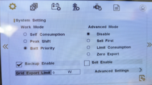
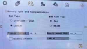
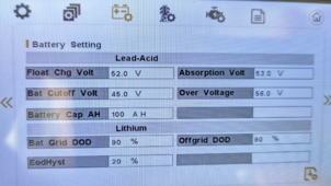
I could use some advice on setup for being a UPS only (grid + battery, no PV).

My present configuration is:

1716649984547.png
1716650040663.png
1716650095954.png

The EG4 batteries communicate over CANbus to the inverter using the Megarevo protocol. That appears to work.

My concerns with the above settings is that the battery is constantly cycling between charge and discharge. This is not just an indication problem, my clamp meter says the same thing. I would have expected the battery to basically sit at zero current for a long period of time, and maybe occasionally get a top up charge every few days or so. But it switches charge/discharge every few seconds.

Also, the unit runs hot, internal temps reading 50-55 C and hot to the touch. This seems weird to me given it is just passing the grid through to the load and is not doing PV and the battery is at 100%.

Any suggestions on how to configure this properly for UPS only mode? I sent email to Watts247, but haven't heard back after a day.

I absolutely must avoid any power flowing back into the grid. I won't even use zero export, all the inverter power must go only to the LOAD connection.

I would really prefer not to dumb down the system to lead acid voltage level controls if I can avoid it.

The unit does do backup very nicely, nothing in the house resets on grid failure.

Mike C.
 
I'm the future owner of the house as specified in the will. In some sense, I already have an ownerships stake in the house. Transferring the deed now simply makes the transfer early.

I suggest you get an opinion on that from a tax attorney, trust attorney, IRS letter, etc.

Not sure how title would be held in your state. In California it is either "Tenants in Common" or "Joint Tenants".
With Joint Tenants, when one dies the other has full ownership. With Tenants in Common, each share can be separately left by will.

If you are left a property by will, it is likely free of estate tax unless total estate exceeds something like $10M. You receive a stepped-up basis to market value. A "Retrospective" a.k.a. "Date of Death" appraisal establishes value the day previous owner died and that is your basis should you sell it. Zero capital gains up to that amount, capital gains and homeowner's exclusion above that.

Those should only apply when you sell. If not inherited and subject to stepped-up basis, all the receipts from capital improvement your parents made decades ago, and purchase records, are needed to determine basis.

In California, if you are added to deed, your 50% or whatever portion would be reassessed for property taxes. (related to our Prop 13). If inherited, it could be reassessed to market, or you could inherit property tax basis, depending on various rules.

I think the choice has huge tax implications. Consult a professional; the few $hundred it might cost could save $hundreds of $thousand in taxes.

Remember: Laws and Sausages ...
This is a Nation of the Lawyers, by the Lawyers, and for the Lawyers.
 
I could use some advice on setup for being a UPS only (grid + battery, no PV).

My present configuration is:

View attachment 217556
View attachment 217557
View attachment 217558

The EG4 batteries communicate over CANbus to the inverter using the Megarevo protocol. That appears to work.

My concerns with the above settings is that the battery is constantly cycling between charge and discharge. This is not just an indication problem, my clamp meter says the same thing. I would have expected the battery to basically sit at zero current for a long period of time, and maybe occasionally get a top up charge every few days or so. But it switches charge/discharge every few seconds.

Also, the unit runs hot, internal temps reading 50-55 C and hot to the touch. This seems weird to me given it is just passing the grid through to the load and is not doing PV and the battery is at 100%.

Any suggestions on how to configure this properly for UPS only mode? I sent email to Watts247, but haven't heard back after a day.

I absolutely must avoid any power flowing back into the grid. I won't even use zero export, all the inverter power must go only to the LOAD connection.

I would really prefer not to dumb down the system to lead acid voltage level controls if I can avoid it.

The unit does do backup very nicely, nothing in the house resets on grid failure.

Mike C.
I don’t use mine as a UPS but try System Settings -> Advanced Settings and enable Time of Use. Set SOC to 100% for each timeframe. I believe that should keep everything flowing through grid unless grid is lost.
 
IIRC, the balancers in the eg4 batteries are passive. Since the batteries are communicating with the inverter, could the constant charge/discharge be the batteries wanting the inverter to keep them topped off as the balancing burns off the higher voltage cells?
 
The battery display says the battery is cycling between STANDBY and DISCHARGE. The SoC remains at 100%.

What I would want, ideally, is the battery charges to 100%, stops charging, and then will only recharge if the SoC falls below 90% or something like that. This would stop this cycling behavior.

There seems to be no setting for that in the system.

Mike C.
 
Suppose this is where it gets confusing when the battery and inverter are talking. Is the inverter cycling because the battery is telling it to?
 
Suppose this is where it gets confusing when the battery and inverter are talking. Is the inverter cycling because the battery is telling it to?
Maybe. I can disconnect the battery, but then the inverter will shut off charging completely. I think it will only charge if set to lithium and has comms. So disconnection will stop all charging.

Mike C.
 
Set it to lead acid, set voltages, and see what happens?

Can the ct's share a common cat5 cable? They only use two wires. It would be easier to use a splitter at both ends, and run one cat5 the 75' vs two cat5 cables? .
 
There seems to be no setting for that in the system.
Typically in some systems there is a rebulk setting but that would be overridden by the closed communication from the BMS. I agree with the other poster who said it is possible the the balancing circuit is causing the fluctuations.
I would also try a TOU setting of 99% for a time after the battery typically gets fully charged. That worked for me on a SolArk to keep the battery from floating at a high voltage for a few hours until my peak period discharge began at 4PM
 
Last edited:
Set it to lead acid, set voltages, and see what happens?
Funny you should say that...

Today we were running the system grid down on battery to do a burn in test. About 3 hours into the test, the inverter shutdown and the backup panel went dark. Battery was at 88%.

The inverter reported a battery comm error. In lithium mode, if the battery comms has an error, the inverter no longer uses the battery and it shut down. My early apparent success getting the inverter to talk to the battery was falsely encouraging and that protocol isn't 100% reliable.

So I disconnected the battery comm cable, reprogrammed the inverter to lead acid/custom settings, used the EG4 settings in the manual for bulk, float, cutoff, etc. Now the system is running again on battery but this time without battery comm. So far, all is well, but we are only 2 hours into this test so far. I intend to run the battery down to 20% or so overnight to check it out.

If this works, and it seems like it will, then battery comms is a failure point and using old style voltage levels will be more reliable. This will also stop the battery charge/discharge cycling, another indication that battery comms wasn't performing well.

What this also means is that my interest in moving the system to Solar Assistant is higher. With SA, I can separately monitor the inverter, battery #1, and battery #2. I can then automate any actions based on battery SoC in SA if I want to.

The Solarman app that comes with the unit is mediocre at best. I am sure SA will be far superior to monitor and control the unit.

Can the ct's share a common cat5 cable? They only use two wires. It would be easier to use a splitter at both ends, and run one cat5 the 75' vs two cat5 cables? .
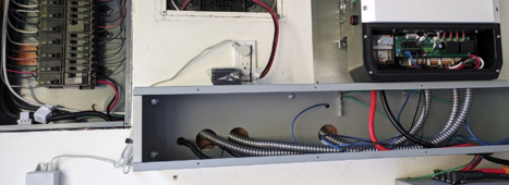
The supplied CTs with the unit have a cable length of about 6 ft or so. For my install that worked nicely. The CTs sit in the bottom of the main panel where the utility feed comes in. I then run them in a small plastic flex conduit to the trough, then they go to the inverter and plug into the RJ45s there. I have maybe 2 ft spare length. It is important to get the CT arrow direction right, and to get L1 versus L2 right.
1716684993969.png

If you were running them further, then I would take one network cable and use two punch down RJ45's at each end. Then plug the CTs in the RJ45s at one end, and use a short patch cable at the other to go to the inverter. You would have to learn which pins are active and workout the signal mapping. Make sure to use pins which are twisted together for each CT (pin 1/2, 3/6, 4/5, 7/8).

The CTs supplied fit my feed cables without difficulty (200 amp service).

Mike C.
 

diy solar

diy solar
Back
Top