


You are using an out of date browser. It may not display this or other websites correctly.
You should upgrade or use an alternative browser.
You should upgrade or use an alternative browser.
I need a large 12V load...
- Thread starter Will Prowse
- Start date
zgk51
New Member
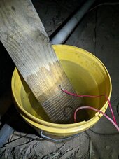
You don't need all these fancy resistors. I was stuck on this same problem a few months ago, looking up all sorts of 12v water heater elements... eventually made a perfect load resistor in 5mins out of steel wire wrapped around a plank of wood and then submerged in a bucket of water!
It was a good ~20amp load for testing my 24v batteries. I then made a second one and connected them in parallel to get more load. Worked well. I ran them for about 16hrs with a victron smart shunt to log the current over time.
I used cheap zinc plated tie wire, perhaps about 0.5mm thick, and about 5m of it wrapped around a wooden plank. I'll try to find a pic...
Ps. I realise the OP is looking for much more power but my point is long lengths of steel wire is resistive enough and the water keeps it cool enough that it won't burn out. I think you could make something similar to mine but with a much higher power.
Attachments
Last edited:
seneysolar
Solar Addict
Nobody wanted to recommend the 10k inverter? 

Warpspeed
Solar Wizard
.
Last edited:
Warpspeed
Solar Wizard
Suggest you try two in series across 12v.A 1Kw electric radiator bar of similar size glows bright red hot.
Those resistors will work fine, but not at 1Kw each.
Prepare for much initial smoke and smell.
Once they turn black they will be fine.
12v at 32A = 384 watts or 192 watts per resistor.
At that estimated temperature rise, you should just be starting to get into the hot smell region, but no smoke. They will still go black over time.
Ten of those maybe 1.9Kw 160 amps, and no drama.
Last edited:
Video is up...
How cool is that!! The resistors worked perfectly!
How cool is that!! The resistors worked perfectly!
Some build shots!!


robbob2112
Doing more research, mosty harmless
I WANT ONE, pretty please
awpatterson217
AWP
I build similar (but way, way smaller) dummy load circuits to test lasers and that looks hilariously big to me. I want one.
Brucey
Solar Wizard
That 2000A smartshunt, is the sideways bolt a thru one so you'd have to remove the left connection to remove the right side if that makes sense.
It's ridiculously big haha but those resistors get insanely hot! Felt like a fire from my distance for the epoch test hahaI build similar (but way, way smaller) dummy load circuits to test lasers and that looks hilariously big to me. I want one.
Yes it goes through it completelyThat 2000A smartshunt, is the sideways bolt a thru one so you'd have to remove the left connection to remove the right side if that makes sense.
robbob2112
Doing more research, mosty harmless
I think you should make them into a box and cremate a turkey in november
I guess I am going to think my Li-time group 24 with bluetooth have a similar overcurrent protection as the trolling motor group 31 version. I think in your video the BMS looked similar. I still have 120 amp breakers straight off the batteries though. Very nice testing setup btw.
WorldwideDave
New Member
That CRIMPER though...very nice.
I found that my local West Marine has one there I can use, but they will not strip or crimp wire for you. They let you use their crimper, though. They will not provide a cutter to strip back the wire.
Also at Home Depot when getting the larger 1/0, 2/0, 3/0 and 4/0 wire, there is only one employee I've met in 6 months that is strong enough to cut the wire with the cutters they have chained to the big rotisserie of wire spools.
Hedges
I See Electromagnetic Fields!
- Joined
- Mar 28, 2020
- Messages
- 21,981
It's ridiculously big haha but those resistors get insanely hot! Felt like a fire from my distance for the epoch test haha
Which will toast the mounting board after a while.
You could put a reflective and insulated sheet under the resistors.
Got fan?

Doesn't take much airflow to greatly reduce the delta-t required to transfer same amount of energy.
I set up something similar with single resistor in a box with fan and vents so an intern could test the power supply evaluation board he implemented for us without exposed HV. (PFC module, 230Vrms to 380VDC)
Yes, adding a fan and mounting on a concrete wall in a few weeksWhich will toast the mounting board after a while.
You could put a reflective and insulated sheet under the resistors.
Got fan?
View attachment 229409
Doesn't take much airflow to greatly reduce the delta-t required to transfer same amount of energy.
I set up something similar with single resistor in a box with fan and vents so an intern could test the power supply evaluation board he implemented for us without exposed HV. (PFC module, 230Vrms to 380VDC)

That was my only concern watching the video "should he really have that high a resistive load mounted to ply?" I was just imagining my grandparents old wire wound heaters the whole time.Yes, adding a fan and mounting on a concrete wall in a few weeks
Also when you do tear it down I'd be interested in how well those isolators did switching while under load. They were switching 60amp if I remember correctly, what were they rated at?
Tbh I think it's the switching off during load that's going to cause issues and you did that via the large switch.
I've looked at that type of isolator before but felt that they may arc badly when opening unless the rear terminals are sunk in something like rtv silicone so I've always shy`d away from using them.
Quattrohead
Solar Wizard
I love that test rig. Kind of thing that I have lashed up in the past for R&D.
outsider
New Member
R= V/I, so you want R = 12 V / 600 A = 0.02 Ohms. 10 ga wire is about .001 Ohms/foot, so 20' of 10 ga is about right. Coil it up and water cool it, like in a fish tank or camping cooler. This is 7200 total watts, or 360 W/foot. That might be a little rough for the insulation even if water cooled, so maybe use bare copper wire. There will be a slight inductance from the fact of being coiled, if the turns all run the same direction, but you can cancel this by folding the wire in half lengthwise and then coiling that up - then the turns will go one way for half the length and then the other way the other half, canceling most of the inductance.Trying to find some 1000W resistors for 12V test loads, but having a tough time! Speciality resistors are not cheap..
I also purchased an 800W 12V car defroster, and it only pulled 300W:
View attachment 227619
I want to create a 300-600A load. Purely resistive.
I could buy a 10kW inverter, and then hook up a ton of light bulbs. But obviously that's not purely resistive.
There has to be an easier way!
Some 12V batteries claim they can pull 300A for 5 seconds. Others 200A for 20 seconds etc. just need a large simple load for these tests.
What would you guys do?
Putting the whole thing in water isn't an electrocution hazard because it's only 12 V.
Does Will own a oscilloscope? (If not, then by next episode I reckon he will have four lol). You could put a o-scope probe across the isolators to see what type of inductive voltage spike you are getting when you interrupt current flow. If you are getting a hundreds of volt spike, then probably the switch is arcing a little and eventually might start being hard to turn on or off as the contacts get smudged.That was my only concern watching the video "should he really have that high a resistive load mounted to ply?" I was just imagining my grandparents old wire wound heaters the whole time.
Also when you do tear it down I'd be interested in how well those isolators did switching while under load. They were switching 60amp if I remember correctly, what were they rated at?
Tbh I think it's the switching off during load that's going to cause issues and you did that via the large switch.
I've looked at that type of isolator before but felt that they may arc badly when opening unless the rear terminals are sunk in something like rtv silicone so I've always shy`d away from using them.
I mean you could turn the lights off and look at the switch to see if it is arcing, but an oscilloscope looks much more engineeringy.
Warpspeed
Solar Wizard
Will has only been running this for tens of seconds at a time..... so far.
And that is perfectly o/k.
Running it for minutes or hours continuously to do, for example, a full battery discharge test would be a very different matter.
And that is perfectly o/k.
Running it for minutes or hours continuously to do, for example, a full battery discharge test would be a very different matter.
efficientPV
Solar Addict
- Joined
- Sep 24, 2019
- Messages
- 1,569
This is what an arc looks like

windsurfer
New Member
- Joined
- Nov 4, 2022
- Messages
- 41
With those currents you might consider adding a redundant master cutoff switch.
OzSolar
Whatever you did, that's what you planned.
I'm pretty sure I'm getting what you're saying about the Ohms calculation but there's still the issue that #10 wire, even if it water cooled, in my book anyways, is going to struggle to not melt in two under 600 amps. Or I am missing something?R= V/I, so you want R = 12 V / 600 A = 0.02 Ohms. 10 ga wire is about .001 Ohms/foot, so 20' of 10 ga is about right. Coil it up and water cool it, like in a fish tank or camping cooler. This is 7200 total watts, or 360 W/foot. That might be a little rough for the insulation even if water cooled, so maybe use bare copper wire. There will be a slight inductance from the fact of being coiled, if the turns all run the same direction, but you can cancel this by folding the wire in half lengthwise and then coiling that up - then the turns will go one way for half the length and then the other way the other half, canceling most of the inductance.
Putting the whole thing in water isn't an electrocution hazard because it's only 12 V.
I built a discharging set up for a 2V FLA cell and a two 16' loops of #12 wire in parallel. It worked great.
Similar threads
- Replies
- 22
- Views
- 889
- Replies
- 3
- Views
- 486
- Replies
- 5
- Views
- 294
- Replies
- 42
- Views
- 1K