You are using an out of date browser. It may not display this or other websites correctly.
You should upgrade or use an alternative browser.
You should upgrade or use an alternative browser.
Seplos CAN BUS RS485 48v 200A 8S-16S BMS
- Thread starter Firechief
- Start date
houseofancients
Solar Wizard
you should use 00 for deye/sol-ark/sunsynk.Trying to get communication is turning out to be just as difficult as I had figured.
Seplos emailed me a firmware update for the Deye, and they said it should work with Sol-Ark as well, which flashing the firmware went smoothly. But in the Battery Monitor app it won't let me set a Can protocol. I've tried setting it to the PN-GDLT, but I just get an error saying it didn't work. Can't figure this part out?
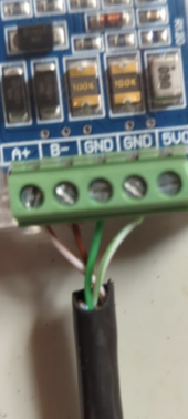
I've tried the wiring configuration suggested in this post https://diysolarforum.com/threads/seplos-can-bus-rs485-48v-200a-8s-16s-bms.20051/post-300832, I've also wired the BMS Side in both Canbus and RS485 like shown in their manual, and the same for the Sol-Ark side based on their manual, which is surprisingly the same wiring.
View attachment 118317
View attachment 118318
I also am a little unsure of which BMS Lithium Batt Modes to select in the Sol-Ark. I assume 00 or 02? If its 02 for Pylontech, which is labeled Modbus, do I need to connect the cable to the Modbus RS485 port on the inverter? And not the Canbus port?
also be aware that the pinout for canbus and modbus (rs485) is different.
don't forget to reset the bms after changing the mode ( reset button)
Lt.Dan
Solar Wizard
Perfect. Thank you.you should use 00 for deye/sol-ark/sunsynk.
Yes, I have tried the Canbus pinout, and the modbus pinouts. The pictures from above are for the Canbus pinouts.also be aware that the pinout for canbus and modbus (rs485) is different.
THIS is something that isn't notated anywhere in any manuals! I will try this.don't forget to reset the bms after changing the mode ( reset button)
I'm awaiting an answer from Seplos as to why changing the CAN protocol inside Battery Monitor app throws an error.
deonbez
New Member
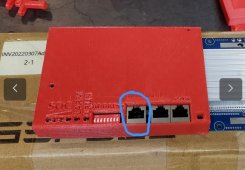
@Lt.Dan : Nice print in red (aka be careful / danger)!I finished the print from Thingiverse. My print quality isn't the greatest, and need to work on a few things (I don't do it very often, and am still learning). But it fits the BMS good, and clips on pretty well. The buttons on the screen dont line up very well, which is preventing the screen from sitting flat at all. Might be able to just take a small dremel and oval the holes a bit to fit better. All in all, its not bad.
@deonbez Very excited to see yours when completed. I would also kind of like to see some ventilation for the heat sink in yours? Not sure if the heat from the heat sink will warp/distort the PLA. Unless your printing it with Nylon or ABS?
I asked my son to add a ventilation area for the BMS heatsink
Will share a photo as soon as I have printed the refined 3D design
How does paralleling them work? If one of the batteries has a problem, it takes them all down?
Or if not, how does it deal with a battery coming online later again with a different state of charge and voltage?
I mean if you build some NMC 10kWh blocks, than a lot of power can be flowing between them if they are not kept in balance (because one has been closed for a while due to some issue)
Or if not, how does it deal with a battery coming online later again with a different state of charge and voltage?
I mean if you build some NMC 10kWh blocks, than a lot of power can be flowing between them if they are not kept in balance (because one has been closed for a while due to some issue)
deonbez
New Member
@Lt.Dan, the 3D design for the Seplos BMS is complete and available at https://www.thingiverse.com/thing:5604549@Lt.Dan : Nice print in red (aka be careful / danger)!
I asked my son to add a ventilation area for the BMS heatsink
Will share a photo as soon as I have printed the refined 3D design
Top is currently printed with Carbon Fibre infused PLA, bottom with PETG. Will see if another material is required.
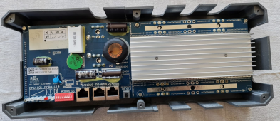
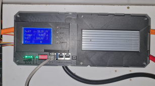
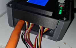
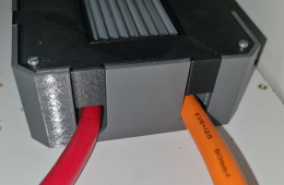
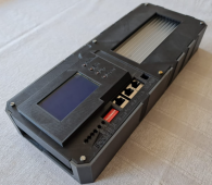
houseofancients
Solar Wizard
good job, nice work@Lt.Dan, the 3D design for the Seplos BMS is complete and available at https://www.thingiverse.com/thing:5604549
Top is currently printed with Carbon Fibre infused PLA, bottom with PETG. Will see if another material is required.
View attachment 119038View attachment 119033
View attachment 119034
View attachment 119036
View attachment 119035
Lt.Dan
Solar Wizard
I am still having a hard time with the comms from Seplos to SolArk, and I'm starting to think its because of the RS485 BMS I have.
Seplos doesn't seem to think that it is a problem, and the firmware flash I put onto it is why I cannot change the communication protocols in the Battery Monitor software, it is locked to the Deye comm protocol now.
I have the documentation from seplos and Sol-Ark as the following:
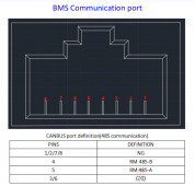
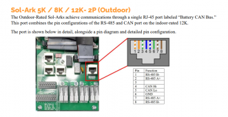
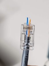
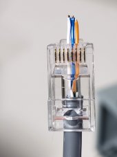
And this is how I currently have my RJ45 cable connected:
Seplos Pin 4 to SA Pin 8 (BLUE WIRE)
Seplos Pin 5 to SA Pin 7 (BLUE/WHITE WIRE)
Seplos Pin 6 to SA Pin 6 (ORANGE WIRE)
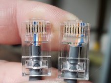
Can anybody tell me if I'm doing something wrong?
Seplos doesn't seem to think that it is a problem, and the firmware flash I put onto it is why I cannot change the communication protocols in the Battery Monitor software, it is locked to the Deye comm protocol now.
I have the documentation from seplos and Sol-Ark as the following:


And this is how I currently have my RJ45 cable connected:
Seplos Pin 4 to SA Pin 8 (BLUE WIRE)
Seplos Pin 5 to SA Pin 7 (BLUE/WHITE WIRE)
Seplos Pin 6 to SA Pin 6 (ORANGE WIRE)

Can anybody tell me if I'm doing something wrong?
duyvietstar
New Member
- Joined
- Jun 11, 2021
- Messages
- 16
For seplos port, you have to count backwards.I am still having a hard time with the comms from Seplos to SolArk, and I'm starting to think its because of the RS485 BMS I have.
Seplos doesn't seem to think that it is a problem, and the firmware flash I put onto it is why I cannot change the communication protocols in the Battery Monitor software, it is locked to the Deye comm protocol now.
I have the documentation from seplos and Sol-Ark as the following:
View attachment 119039
View attachment 119040
And this is how I currently have my RJ45 cable connected:
Seplos Pin 4 to SA Pin 8 (BLUE WIRE)
Seplos Pin 5 to SA Pin 7 (BLUE/WHITE WIRE)
Seplos Pin 6 to SA Pin 6 (ORANGE WIRE)
View attachment 119041
Can anybody tell me if I'm doing something wrong?
Lt.Dan
Solar Wizard
Based on the way you view the plug, I can't see that I have it wrong? What sucks is they don't specify if you are looking at the inside of the plug, or the end of it? Im assuming I'm looking at the inside.For seplos port, you have to count backwards.
duyvietstar
New Member
- Joined
- Jun 11, 2021
- Messages
- 16
You can't connect then it mean you are not correct. Let's try agian, and count backwards at port seplosBased on the way you view the plug, I can't see that I have it wrong? What sucks is they don't specify if you are looking at the inside of the plug, or the end of it? Im assuming I'm looking at the inside.
Lt.Dan
Solar Wizard
Ok, so pin 4, 5, and 6, counted backwards from originally.You can't connect then it mean you are not correct. Let's try agian, and count backwards at port seplos
Seplos plug on the left, SA on the right.
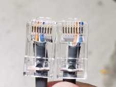
Still no luck. When I activate the Lithium Batt checkbox, and set it to 00. It enabled a new tab for lithium battery info, but its all just 0's. No info. On the front screen there is just a " ! " with a triangle around it, saying there is an error. I even went as far as shutting the Sol-Ark down completely, and shutting down the BMS with the reset button, then powering them both back up, and still nothing.
deonbez
New Member
For RS485 Seplos BMS (which I understand your have), I also experienced you cannot change the protocol in the PC BMS monitor application.I am still having a hard time with the comms from Seplos to SolArk, and I'm starting to think its because of the RS485 BMS I have.
Seplos doesn't seem to think that it is a problem, and the firmware flash I put onto it is why I cannot change the communication protocols in the Battery Monitor software, it is locked to the Deye comm protocol now.
As from the SolArk manual (see below), have you tried the protocol 02.
I would also try using pins 1/2 on the inverter instead of pins 7/8
Also try swapping pin 4 and 5 on the BMS side
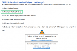
Last edited:
Lt.Dan
Solar Wizard
I have tried protocol 02 before, I've actually tried every protocol each time I make a change to the pinout. Just because, I have tried 02 again, and still no luck.For RS485 Seplos BMS (which I understand your have), I also experienced you cannot change the protocol in the PC BMS monitor application.
As from the SolArk manual (see below), have you tried the protocol 02.
Also instead of using pins 7/8 on the inverter use pins 1/2
I would also try using pins 1/2 on the inverter instead of pins 7/8
Also try swapping pin 4 and 5 on the BMS side
View attachment 119080
I swapped pin 7 and 8 to 1 and 2 and tried again. No luck.
I swapped pin 4 and 5 on the BMS side. No luck.
deonbez
New Member
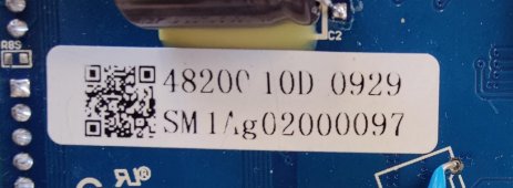
@Lt.Dan, apologies for asking again if you already confirmed it somewhere else, but are you sure you have a RS485 model, indicated by 10D as below?I have tried protocol 02 before, I've actually tried every protocol each time I make a change to the pinout. Just because, I have tried 02 again, and still no luck.
I swapped pin 7 and 8 to 1 and 2 and tried again. No luck.
I swapped pin 4 and 5 on the BMS side. No luck.
Lt.Dan
Solar Wizard
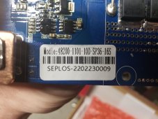
Dont apologize! I feel this problem is being way more annoying than it should be! Yes, mine is 10D as well:@Lt.Dan, apologies for asking again if you already confirmed it somewhere else, but are you sure you have a RS485 model, indicated by 10D as below? View attachment 119135
deonbez
New Member
@Lt.Dan , see this post with the firmware I received from Seplos support and used successfully for the RS485 BMS version. This firmware ensures the BMS acts for the inverter like a RS485 Pylontech battery.Thank you for the detailed explanation.
I managed to get the RS485 version (marked as 10D Model) of the BMS going with our Sunsynk inverter after loading a new RS485 firmware version (see attached not for CAN Version) as received from Seplos support. As previously mentioned, they indicated I don't have to set the RS485 Protocol from the Battery monitor PC application. As I only have one BMS, all DIP switches are off.
Cable pinouts used:
BMS RS485 (called CAN) <-> Sunsynk Inverter RS485:
4 <-> 2 (or 7)
5 <-> 1 (or 8)
Sunsynk is set to RS485 and Protocol 12 (for Pylontech)
Lt.Dan
Solar Wizard
@deonbez that is coincidentally the same firmware they gave me! Or at least it has the exact same file name.@Lt.Dan , see this post with the firmware I received from Seplos support and used successfully for the RS485 BMS version. This firmware ensures the BMS acts for the inverter like a RS485 Pylontech battery.
Lt.Dan
Solar Wizard
YES, using the port labeled "CANBUS". Even though its an RS485 version....
Lt.Dan
Solar Wizard
Well in my process of attempting to get the communication to work, I set the display screen down on the metal case of the battery (hindsight), and it somehow shorted out the BMS and let out the mystery smoke. This happened on Nov 4th, and I didn't post about it because I wanted to get Seplos' response first.
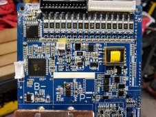
There is 3 components that are totally toasted that I can see. What a bummer. So I sent them an email on the 6th asking if there was any warranty on this, or anything. No response. I sent another email just to follow up if they got my email on the 9th and no response still.
Does anybody know of someone else I can talk to? I have been dealing with Alan the Postsale Engineer, and maybe I'm just barking up the wrong tree?
Thankfully I purchased 2 BMS's, so I was able to swap in my 2nd and was up and running in no time.
Good day, dear forum members!
I, too, was plagued by the problem of Diode D4. It took me a whole month to find a replacement for this diode and replace it.
I also ordered another new BMS from Seplos at the same time.
I received it yesterday too.
I compared it visually - they are different boards in layout, components and markings.
I understand the capabilities are different as well. This board can now do both CAN and RS485 at the same time.
The board marking is now 10E.
Has anyone already had experience with these new boards?
Is there any documentation?
Will the software from the old board, the adapter, and the LCD panel fit the new board?
I made a request to the reseller, waiting for an answer.
Before I do something stupid the first time I connect I would like some answers to my questions before connecting.
I, too, was plagued by the problem of Diode D4. It took me a whole month to find a replacement for this diode and replace it.
I also ordered another new BMS from Seplos at the same time.
I received it yesterday too.
I compared it visually - they are different boards in layout, components and markings.
I understand the capabilities are different as well. This board can now do both CAN and RS485 at the same time.
The board marking is now 10E.
Has anyone already had experience with these new boards?
Is there any documentation?
Will the software from the old board, the adapter, and the LCD panel fit the new board?
I made a request to the reseller, waiting for an answer.
Before I do something stupid the first time I connect
I will answer my own questions 
Alan from after-sales support sent me the answers to my questions.
1. the stubs to the battery cells are interchangeable, which is not surprising.
2. The LCD panel will also fit the old BMS version 10C.
BT is built into the new version of the panel, which is 004. But I don't need it at all.
3. The software of the new version, 2.1.9.
It can be used together with the old version of the BMS.
4. There is a new user manual. And a new manual for Battery Monitor 2.1.9.
How to post on the forum, in the instructions section, I do not know.
Alan answers quickly and will send if anyone asks for it.
P.S. Uploaded to resources.
Last edited:
Well, that's a shame, isn't it? One awkward move and the board could be thrown in the trash.Well in my process of attempting to get the communication to work, I set the display screen down on the metal case of the battery (hindsight), and it somehow shorted out the BMS and let out the mystery smoke. This happened on Nov 4th, and I didn't post about it because I wanted to get Seplos' response first.
View attachment 120258
There is 3 components that are totally toasted that I can see. What a bummer. So I sent them an email on the 6th asking if there was any warranty on this, or anything. No response. I sent another email just to follow up if they got my email on the 9th and no response still.
Does anybody know of someone else I can talk to? I have been dealing with Alan the Postsale Engineer, and maybe I'm just barking up the wrong tree?
Thankfully I purchased 2 BMS's, so I was able to swap in my 2nd and was up and running in no time.
Your way to Seplos for a new Model 10E board.
Similar threads
- Replies
- 26
- Views
- 888
- Replies
- 2
- Views
- 219
- Replies
- 4
- Views
- 242
- Replies
- 22
- Views
- 2K
- Replies
- 6
- Views
- 1K


