diy solar

diy solar

A123, Battery EVO, Big Battery, Tech Direct, etc.

Awesome, those were the same units I was going to purchase. I plan on using dual LV6548s to charge these from PV array. I looked up the spec sheet and here's what it says...

"Utility Charging Mode MODEL LV 6548 Charging Current (UPS) @ Nominal Input Voltage 120A

Bulk Charging Voltage Flooded Battery 58.4Vdc AGM / Gel Battery 56.4Vdc
Floating Charging Voltage 54Vdc
Overcharge Protection 66Vdc
Charging Algorithm 3-Step"

So, doesn't look like I should push more than 48v out of these modules if I purchase them.
 
Well, let the journey begin. I just bought the remaining modules. Seller accepted an offer of $750/ea so if this works out I think it's a killer deal. How many BMS units will I need? 4? One for each bank?
 
Would you mind sharing the Alibaba link for the BMS units you ordered. I'm not in a huge rush and can wait on shipping if it saves me money from spending $200/ea at 1850 Battery
 
FYI: This is the pinout if the BMS connector if you're looking at the end of the female connector, rotated up after you removed it. The clip should be at the bottom, and I think the bottom left is pin 1:

TXTS0 (0V)S0 (0V)XS5 (16.5V)S6 (19.8V)S6 (19.8V)
TTTS1 (3.3V)S2 (6.6V)S3 (9.9V) S4 (13.2)XX

I didn't identify the individual temperature sensors. I don't know what type they are, although they're probably pretty standard thermistors. At some point it might be fun to pull one off and try to calculate the temperature profile, but it's probably not worth it. X means there's no wire connected.
 
I decided to try another idea for making 48V packs out of these. The idea is to just put them all in series, treating them as one big pack, and make two cuts after the 16th and 32nd cell. With 8 of these batteries, that would make 3 full 48V packs exactly. Unfortunately, so far, soldering to the battery bars has been a bust! There's just too much thermal resistance, at least for my (not bottom of the line) Weller. I'm sure I could get it to work with a higher power soldering iron, but I'd be afraid of damaging the batteries.

The best solution I've come up with so far is to use a busbar to clamp wire into the ridges of the battery busbars. This would require drilling 2-3 screw holes, but if the screws hold, I believe that would provide a solid connection for the wire.

I'd be happy to hear any suggestions that others might have.
 
My heat gun died half way through the project, so it's been delayed. I have a new one now, though.

I'm also still working on ideas for connecting to the battery bar. I was able to get some 10 awg wire soldered with a higher power soldering iron. Multiple 10 awg wires in parallel would likely work, but I'm working on another idea first.

I have a 1/0 ground strap on order, which should be in tomorrow. I had originally planned on soldering that to the battery bar, but I'm first going to try soldering it to a copper bar, that I would then screw onto the battery bar. I think that would be better for the battery than multiple solder joints.

I also made a design for a 3d-printed bracket that uses the screw holes on the sides of the battery and wouldn't require drilling into the battery bar. I have a version sitting in front of me that I might test. The idea would be to clamp the 7 awg wire from the BMS directly to the battery bar. I think it could work, but it would require printing in a material that's not going to bend easily. I have some carbon fiber PETG and/or PLA that I could try.
 
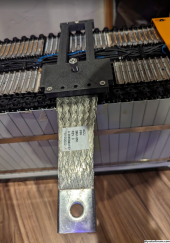
I got the battery straps in today, and I think they're going to work very well. They're supposed to be equivalent to 1/0 wire, and I can believe that. I used a cutoff saw to cut it down the middle, and the strap is nearly as wide as the length of battery bar.

I printed a bracket to clamp the strap to the battery using a 1"x3"x1/8" bar of copper, and I'm sure it's contacting far more than a 1/0 lug would. You can see the bracket below, printed in carbon fiber PETG. The copper bar is under the screw, and the screw can apply additional pressure on the plate if necessary, but I don't think it is necessary. The middle three screws could be used to help hold the strap in place by applying some solder to the strap and drilling some holes, but I don't think it's necessary.

There's a couple of minor adjustments that I want to make to the bracket, and I'll probably combine it with another one, facing the other direction to put the other side of the strap on the bar in the upper left. I'll also heat shrink over the straps, and cut the battery bar just to the left of the bracket to split the pack.

This is the ground strap that I bought: https://www.amazon.com/dp/B008DEY1IC

1694585791800.png
 
No. I'm going to test just one pack at 48V first, which I can do without cutting. The only issue I see with cutting is that many of the BMS wires are right where you would want to cut. You can see that in the picture above. If I cut on the correct side (the left side in this case I believe), it should be okay, but it may pop the wire off. It's a small wire, though, so relatively easy solder if that happens.

BTW, I did a test to see how screws might hold in the battery bars, and I think it would work well. I just drilled a hole for a normal 3mm screw, and it seemed solid. I think a #8 or so self threading screw would work pretty well. 3-4 of those through the copper bar that I'm using should work well. You want to limit the drill depth, of course, but there's quite a bit of room between the bars and the actual batteries.
 
No. I'm going to test just one pack at 48V first, which I can do without cutting. The only issue I see with cutting is that many of the BMS wires are right where you would want to cut. You can see that in the picture above. If I cut on the correct side (the left side in this case I believe), it should be okay, but it may pop the wire off. It's a small wire, though, so relatively easy solder if that happens.
How is this possible considering all the modules together end up being above 48v without cutting anything out? I'm only asking because it would make life SOOOOO much easier if I didn't end up needing to cut anything out.


BTW, I did a test to see how screws might hold in the battery bars, and I think it would work well. I just drilled a hole for a normal 3mm screw, and it seemed solid. I think a #8 or so self threading screw would work pretty well. 3-4 of those through the copper bar that I'm using should work well.
You're talking about the battery bars to connect each of the (2) 48v packs to one another?

You want to limit the drill depth, of course, but there's quite a bit of room between the bars and the actual batteries.
This is comforting news in terms of modification to suit.
 
How is this possible considering all the modules together end up being above 48v without cutting anything out? I'm only asking because it would make life SOOOOO much easier if I didn't end up needing to cut anything out.
If you connect to a battery bar in the middle of the pack, the batteries beyond where you connect to are not part of the pack, so they don't have to be disconnected. If you don't care about losing the two cells going from 18S to 16S, and you connect in the middle like I'm planning on doing (at least initially), and you don't have to cut the batteries apart.

You're talking about the battery bars to connect each of the (2) 48v packs to one another?
In my picture above, under the big screw in the middle is a 1x3 inch copper bar 1/8 inch thick. I'm holding it down with the 3D printed bracket, but it could be screwed into the bar on the battery instead.

It's actually not in the right spot to make a 48V battery. The bar in the upper left, on the other side, is the positive terminal of the 4th battery in that pack, so, my plan is to put the strap on that bar, which would then be the positive terminal (48V) of the entire pack. The negative terminal of that pack would be connected to the positive of another full pack, and the negative terminal of that to the positive of another to make the full 48V.

I'll probably have it wired up tomorrow, so I'll take a picture. My son and I lugged that battery back downstairs to the garage earlier, and I just have to lug two more from the other garage and wire it up. They're not light... :)
 
If you connect to a battery bar in the middle of the pack, the batteries beyond where you connect to are not part of the pack, so they don't have to be disconnected. If you don't care about losing the two cells going from 18S to 16S, and you connect in the middle like I'm planning on doing (at least initially), and you don't have to cut the batteries apart.
How interesting. Really? I always figured all the pouches are tied together in the module itself so you couldn't just bypass any single one or more of them. I suppose bypassing them also leaves them alone in case you ever needed to cut one out and replace a bad cell in the rest of the batch

So much to learn about battery modules, wow ?

Can't wait to see the progress!
The two extra cells are not being bypassed, they're at the end of the chain. There is only one end connected. It's like shortening a chain by connecting to a link that is not at the end. The remaining links will just dangle and not bear any of the weight.

You could use those cells as replacements for any that might go bad, but then you would have to cut the connections to the bad cell and the replacement cell and wire it in place, which would not be easy. I'm not sure it would be worth it.
 
The two extra cells are not being bypassed, they're at the end of the chain. There is only one end connected. It's like shortening a chain by connecting to a link that is not at the end. The remaining links will just dangle and not bear any of the weight.

That makes sense!

You could use those cells as replacements for any that might go bad, but then you would have to cut the connections to the bad cell and the replacement cell and wire it in place, which would not be easy. I'm not sure it would be worth it.

Yeah, good call.
 
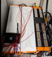
It's still a mess, but I did get the packs wired together in a 48V configuration with the JK BMS:

1694756211633.png

The BMS is connected to the negative terminal, and the ground strap is the positive, and the BMS is working, at least it's balancing. I plan to finish wiring it up and test charging/discharging it this weekend.
 
Looks awesome so far! can't wait to get mine in and start working on the setup. I'm debating between ordering the JK BMS or going with an Overkill BMS. Overkill maxed out at 100a though so I'm torn.

Have you happened to figure out where these modules came from? I asked Greentec but the only specs they could give me were for the individual pouches. I noticed on the eBay listing they cite Panasonic as the brand but no searches of the actual model/sn # has turned anything up.
 
I don't know where they come from, but one of mine is a bit different from the others, in that it has a label on the top, rather than the side (or in addition to the side). They also come in positive and negative polarity, which I think changes the position of the terminals, and why the wiring of my three above is a bit odd. The first two are positive, and the last one is negative. The other ones that I have are all positive.

I also decided to try screwing down the copper bar directly to the battery bar, over the ground strap, and I think I like that better. I did strip the threads on one of the 4 screws that I put in, so you have to be careful how tight you make them, but I was going pretty tight. I made a total of 6 holes, so I'll probably be a bit more careful with the last two and use a torque driver - at least so I know what is too much if I strip another one.
 
Back
Top